• Steel Soldiers now has a few new forums, read more about it at: New Munitions Forums!

  • Microsoft MSN, Live, Hotmail, Outlook email users may not be receiving emails. We are working to resolve this issue. Please add support@steelsoldiers.com to your trusted contacts.

Restoration of FAV #0010

Mogman

Moderator
Staff member
Moderator
Steel Soldiers Supporter
6,945
9,606
113
Location
Papalote, TX
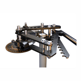
This might work and is not crazy money. Bought one for work and the thing is amazing.


Smallest die set for 1" tubing is 3" Center Line Radius - maybe that is small enough.

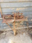
Come to think, I have something very similar out in one of my barns, mid century metal working tool that the wife picked up at auction and it came with a bunch of dies, now to try and find it though...
I can't remember the brand but it was still being made and many dies were available.
That bender is nice and if I was 30 years younger I would invest in one, unfortunately now I would never get the value back before the estate sale:cry:
EDIT, this is the model I have, not this one but one just like it, the search begins:)
Bender.jpg
dies with CLR on the 1" od from 2 1/4-8"
 
Last edited:

Mogman

Moderator
Staff member
Moderator
Steel Soldiers Supporter
6,945
9,606
113
Location
Papalote, TX
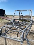
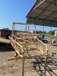
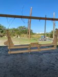
Well despite the shop electrical disaster which cause a couple hours or wire pulling I finished the welding to the FAV chassis.
I replaced the butchered chassis tubing under the dash, added the two missing Dzus plates missing from the front of the roof area and punched the new Dzus holes in the dash, the original FAV only had three Dzus buttons holding the dash in and that was all that holds the dash and they were not evenly spaced for some unknown reason so I took a little creative license and only used the original Dzus plate on the far drivers side and installed five total Dzus buttons, evenly spaced.
Actually the windscreen covers this area and the bottom of the windscreen (have to be careful not to call it a windshield or it will need wipers) is painted so all this purdy work will not be seen anyway!
I also welded up and ground down all the excess holes in the chassis.
EDIT, the Dzus self ejecting buttons are not riveted in place yet, that is why they all do not look "straight" dang things cost 4 bucks apiece so they do not get riveted in place just yet.
Of course all the Dzus springs I installed will have to be drilled out because you do not want to paint Dzus springs if you can avoid it and they and the rivets are rather cheap anyway.
And I wanted to make sure that was all aligned correctly.
 

Attachments

Last edited:

Mogman

Moderator
Staff member
Moderator
Steel Soldiers Supporter
6,945
9,606
113
Location
Papalote, TX
Getting the front end ready for blasting.
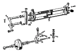
A quick lesson in bug front ends, the pre 1966 VW used a link pin front suspension, 66 and later used a ball joint front end, evidently the link pin was stronger as just about all the off road suspensions are link pin, the original front end used a set of leaves in a torsion configuration, there was two sets of leaves one set in each of the two "beams", they connected in the center using a square fitting that the leaves passed through and a grub screw to secure.
Beetle_front_end.gif
So when they decided they needed a wider front end they installed two sets of square fittings and grub screws and used two complete sets of springs, simply cutting off somewhat less than half of the original springs, the Chenowth built front end on the FAV is 9" over, which is a little unusual, the normal oversize is 6 and 8"
But regardless a set of oversize leaves will work in any oversize front end. (already cut)
Simple enough to figure out the oversize, just measure center to center on the grub screws.
To enhance the front end adjusters are added, about 1 inch of adjustment here makes about 8" difference in height.
The special grub bolts and adjuster bolts have been replaced with standard bolts to make clean up after blasting and painting easier and to protect the threaded parts.
IMG_20221014_165126728.jpg
I wish I had taken a before picture, this adjuster was BADLY mangled, I had to straighten it out and then carefully cut the old nut out with a torch, then weld a new nut in place, not perfect but will do.
IMG_20221014_165121019.jpg
Several of the leaves were broken off, this was about half of them, the rest got blasted out,,this front end really needed some serious TLC.
IMG_20221014_164156922.jpg
Originally it has 8 bushing, two per side per beam, they were made of what looks like a brown phenolic material, as you can see a couple of them were pretty chewed up, in fact one of the outside bushings was pushed into the beam making it useless.
IMG_20221014_164315388.jpg

The replacement bushings are one piece, inside bushing, outside bushing and seal all in one!
IMG_20221014_164415090.jpg
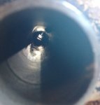
This front end was Packed from one side to the other in 30+ years of grease, what a mess!!!!
Nice to be able to see all the way through the beams!
IMG_20221014_165850953.jpg
Of course I have to dissemble and clean all of this again after blasting/painting
I also protected the two areas on the chassis where the numbers are stamped, the factory chassis plate and the area where the military stamped the serial number, both a very lightly stamped and are hard to read with any paint on them so I want to make sure nothing happens there, I used some .040" high density poly wrapped with a tin can..
IMG_20221011_171550124.jpg
IMG_20221011_171606472.jpg

I also put bolts into any threaded holes on the chassis and any parts going to be blasted.

So we are loaded and waiting to get a coordinated time to drop it off to be blasted and primed with an epoxy primer, I will be doing the painting!
 
Last edited:

Mullaney

Well-known member
Steel Soldiers Supporter
Supporting Vendor
7,724
19,775
113
Location
Charlotte NC
Getting the front end ready for blasting.
A quick lesson in bug front ends, the pre 1966 VW used a link pin front suspension, 66 and later used a ball joint front end, evidently the link pin was stronger as just about all the off road suspensions are link pin, the original front end used a set of leaves in a torsion configuration, there was two sets of leaves one set in each of the two "beams", they connected in the center using a square fitting that the leaves passed through and a grub screw to secure.
View attachment 882033
So when they decided they needed a wider front end they installed two sets of square fittings and grub screws and used two complete sets of springs, simply cutting off somewhat less than half of the original springs, the Chenowth built front end on the FAV is 9" over, which is a little unusual, the normal oversize is 6 and 8"
But regardless a set of oversize leaves will work in any oversize front end. (already cut)
Simple enough to figure out the oversize, just measure center to center on the grub screws.
To enhance the front end adjusters are added, about 1 inch of adjustment here makes about 8" difference in height.
The special grub bolts and adjuster bolts have been replaced with standard bolts to make clean up after blasting and painting easier and to protect the threaded parts.
View attachment 882045
I wish I had taken a before picture, this adjuster was BADLY mangled, I had to straighten it out and then carefully cut the old nut out with a torch, then weld a new nut in place, not perfect but will do.
View attachment 882047
Several of the leaves were broken off, this was about half of them, the rest got blasted out,,this front end really needed some serious TLC.
View attachment 882048
Originally it has 8 bushing, two per side per beam, they were made of what looks like a brown phenolic material, as you can see a couple of them were pretty chewed up, in fact one of the outside bushings was pushed into the beam making it useless.
View attachment 882069

The replacement bushings are one piece, inside bushing, outside bushing and seal all in one!
View attachment 882050
This front end was Packed from one side to the other in 30+ years of grease, what a mess!!!!
Nice to be able to see all the way through the beams!
View attachment 882055
Of course I have to dissemble and clean all of this again after blasting/painting
I also protected the two areas on the chassis where the numbers are stamped, the factory chassis plate and the area where the military stamped the serial number, both a very lightly stamped and are hard to read with any paint on them so I want to make sure nothing happens there, I used some .040" high density poly wrapped with a tin can..
View attachment 882057
View attachment 882067

I also put bolts into any threaded holes on the chassis and any parts going to be blasted.

So we are loaded and waiting to get a coordinated time to drop it off to be blasted and primed with an epoxy primer, I will be doing the painting!
.
You have definitely been steady at it...
This is really going to be an amazing ride when you are finished.
Can't wait to see it back from the blasting shop!
 

Mogman

Moderator
Staff member
Moderator
Steel Soldiers Supporter
6,945
9,606
113
Location
Papalote, TX
The front end on the FAV is a strange duck.
It was built by Chenowth, most oversize beams were built by Warrior.
When I first measured it I thought it was a 9 1/4" (stock beam tube width is 34 1/4" my beam tubes are close to 43 1/2", = 9 1/4") but measuring the grub screws center/center showed it to be a 9" over. (this IS the definitive measurement for beam front ends)
So why the heck the 1/4" discrepancy??
So as it turns out they built this front end to use O rings instead of the stock width seal on the ends of the beam tubes.
It was originally built like this.
IMG_20221017_095805393.jpg
IMG_20221017_095922896.jpg
With two driven in bushings that are made of what looks like phenolic material (brown and rather brittle)
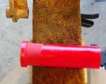
But all stock seals are much wider as seen in this "all in one bushing/seal"
IMG_20221017_095937679.jpg
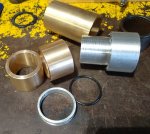
This explains why I was scratching my head for so long, obviously no "stock" seal or seal/bushing is going to work out of the box, the tubes are just too wide so I found these and they will allow me to use the O rings as it was originally set up to use..
bushings.JPG
They are made of Delrin which is much more durable than Urethane and also is happy with standard chassis grease, unlike urethane.
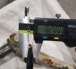
They are .005 larger in dia. than the urethane bushings so it takes a little more to drive them in and must be reamed to size, then they are actually anchored in place by the grease fitting, I also found some 5mmX38mmX48mm replacement O rings
EDIT I am also having to replace the torsion leaves, many are broken, they obviously beat the crud out of these!!
 
Last edited:

Mullaney

Well-known member
Steel Soldiers Supporter
Supporting Vendor
7,724
19,775
113
Location
Charlotte NC
The front end on the FAV is a strange duck.
It was built by Chenowth, most oversize beams were built by Warrior.
When I first measured it I thought it was a 9 1/4" (stock beam tube width is 34 1/4" my beam tubes are close to 43 1/2", = 9 1/4") but measuring the grub screws center/center showed it to be a 9" over. (this IS the definitive measurement for beam front ends)
So why the heck the 1/4" discrepancy??
So as it turns out they built this front end to use O rings instead of the stock width seal on the ends of the beam tubes.
It was originally built like this.
View attachment 882351
View attachment 882352
With two driven in bushings that are made of what looks like phenolic material (brown and rather brittle)
But all stock seals are much wider as seen in this "all in one bushing/seal"
View attachment 882353
This explains why I was scratching my head for so long, obviously no "stock" seal or seal/bushing is going to work out of the box, the tubes are just too wide so I found these and they will allow me to use the O rings as it was originally set up to use..
View attachment 882354
They are made of Delrin which is much more durable than Urethane and also is happy with standard chassis grease, unlike urethane.
They are .005 larger in dia. than the urethane bushings so it takes a little more to drive them in and must be reamed to size, then they are actually anchored in place by the grease fitting, I also found some 5mmX38mmX48mm replacement O rings
.
Nice that you were able to find a "stock part" that will do the job!
 

Mogman

Moderator
Staff member
Moderator
Steel Soldiers Supporter
6,945
9,606
113
Location
Papalote, TX
I was working on the hood today and uncovered some numbers, clearly RV0008
Not sure what to make of it "Recon Vehicle 0008"?
The FAV has a different chassis than the first 8 remote controlled vehicles that were "borrowed" from the Navy (before they ordered the 120 FAVs) so I doubt it stands for "remote vehicle"
And it appears to be over the desert tan so it looks like it was applied after it went to Nevada, interesting..
IMG_20221020_160219900.jpg
 

Mogman

Moderator
Staff member
Moderator
Steel Soldiers Supporter
6,945
9,606
113
Location
Papalote, TX
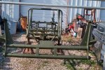
The chassis and front beams came home today, had to stop at good ol Harbor freight on the way to pick up some painting supplies and Sherwin Williams tomorrow for the important stuff, going to use Rapco 34079 for the base coat.
IMG_20221106_095441772_HDR.jpg
 

Mogman

Moderator
Staff member
Moderator
Steel Soldiers Supporter
6,945
9,606
113
Location
Papalote, TX
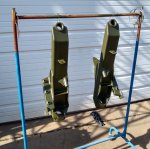
Well I never said I was a painter even though I have pumped allot of paint, this was my first time using a HVLP gravity feed gun but it did not take long to get it dialed in.
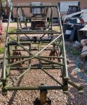
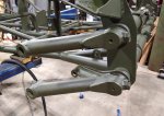
This thing was a ROYAL PITA to paint but it is now GREEN!
At least now I can get back to work on it, plan on having a rolling chassis in 2 weeks
Those trailing arms are about the biggest thing I can get in my blast cabinet, takes allot of work to get them looking like that!
 

Attachments

Last edited:

mgFray

Well-known member
Steel Soldiers Supporter
712
984
93
Location
Southern Minnesota
Looks good. Do you have any idea if the vehicle would have originally been painted in pieces (green or tan or...)? Or was it assembled with some factory color and sprayed as a (nearly) completed vehicle by the military?
 

Mogman

Moderator
Staff member
Moderator
Steel Soldiers Supporter
6,945
9,606
113
Location
Papalote, TX
Looks good. Do you have any idea if the vehicle would have originally been painted in pieces (green or tan or...)? Or was it assembled with some factory color and sprayed as a (nearly) completed vehicle by the military?
It was delivered with most of it painted black the engine and trans were natural.
The military first painted it green, the samples I found on the vehicle were 34079 forest green which would be correct for circa 1982-3.
As far as I can tell all the Army FAVs were green 4 color camo, which was also correct for the time period.
You have to remember our #1 enemy at the time was The USSR, some of the FAVs were deployed in Korea also.
It looks like the DOE painted theirs desert camo
The first paint job the Army gave it was done rather well, I can see the gauges were even removed but I assume it was mostly complete.
This was not true of the DOE, they just taped over some of the stuff and had at it!
As far as I can tell the 16 that were sent to the DOE were sent early, probably before 1984 when the ones in WA were all sent in for some kind of a "rebuild" so what paint scheme they had then if different I have not figured out.

EDIT, the first paint job was likely done when all of the 120 were ripped apart, and things like the side baskets, rear basket, the 15 gal fuel tank and the three lever light switch along with the bastardized M151 wiring harness was installed.

As the story goes the army had "borrowed" 8 Chenowth target drones and had "played" with them for a while, so they would probably already knew what mods they wanted to make to the FAVs when they got to Ft Lewis.
 
Last edited:

Mogman

Moderator
Staff member
Moderator
Steel Soldiers Supporter
6,945
9,606
113
Location
Papalote, TX
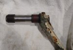
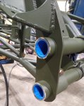
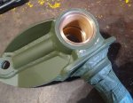
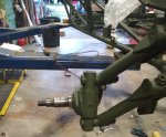
The front end needed some major TLC, the only thing that retains the front trailing arms are the leaf springs and on one of the trailing arms all the leaves were broken or loose so the rest of the suspension was the only thing holding it together, on the king pins all the retaining snap rings had been over expanded which for one thing let them turn in the grooves causing wear on the snap ring grooves and one of them had completely come out of its groove causing the spindle to be out of place, what a mess!
I was concerned when I decided I have to use the same O ring type seal on the trailing arms that the unsupported Delrin bushing would move even though the grease fittings were supposed to "fix" their position, this fear was pretty much alleviated when I drove the bushing into the beam tubes, it took the largest rubber sledge hammer I had and even then the XYL had to hold a hardwood board in place while I drove them the last 1/2" into the tubes with a real sledge hammer.
IMG_20221111_174741434.jpg
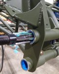
Then of course they had to be reamed to fit.
IMG_20221111_174754000.jpg
So then I was able to install the torsion springs and trailing arms, which is somewhat of a PITA.
IMG_20221111_175527893.jpg
So now on to the king pins, I am not going into a long explanation why I (and all major OEM manufactures that built king pin front ends) do not think the original needle bearings are a good "fit" for king pins, I decided to fit bronze bushings instead.
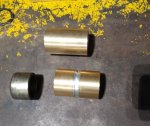
I found some nice cast bronze bushing that were 3" long.
The original setup used two caged needle bearing with an aluminum spacer between them to facilitate the grease going around the king pin, into the hole in the king pin and lubricating the link pins.
So I figured that would work, so I cut the bushings to the original length of the bearings (1.25") with a parting tool on my lathe.
The bearing are inset into the bore in the spindle to give the correct "crush" for the O ring seals used on the king pins so I cut a tool to press in the bushings on the lathe, the original inset was .090" which I figured was not enough crush for a .100" O ring so I started with .065" which was too tight, I ended up cutting the tool to inset the bushings .085" after trial fitting so they were probably correct to begin with, of course these bushings must be reamed to fit also.
The link pins and bushings had no wear at all so that was good!
IMG_20221113_172253620.jpg
IMG_20221114_110428278.jpgIMG_20221116_105444959.jpgIMG_20221116_171115226.jpg
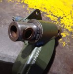
Here you can see how the king pin is fixed to the spindle, a snap ring against a thick arbor shim and the unseen O ring under the washer to seal the king pin.
One of the link bushings must be pressed out to allow disassembly of the king pin (shown already re-installed)
IMG_20221116_171808527.jpg
There is one glaring engineering flaw I did not address:
Ideally the snap ring and arbor washer should stay stationary with the king pin and the movement between the king pin and spindle should be between the arbor shim and the spindle where there is some lubrication along with the seal, but there is nothing keeping arbor washer from turning with the spindle causing the wear to be between the washer and the snap ring or the washer AND the snap ring from turning with the spindle causing the wear to be the snap ring groove, which I observed when going through the tear down.
Don't get me wrong this setup would do the Baja 1000 no sweat, which is the basic design to begin with.
So we endeavor to persevere..
 
Last edited:

Mogman

Moderator
Staff member
Moderator
Steel Soldiers Supporter
6,945
9,606
113
Location
Papalote, TX
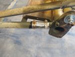
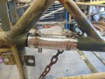
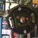
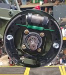
Well I have a rolling chassis, the suspension, steering and brakes themselves are complete with the exception of the tie rods and of course the shocks will not get installed until it is ready to drive, one of the tie rods has a seized rod end and it looks like they even bent the rod trying to turn it. (anybody ever heard of never seize?)
I have a custom exact duplicate for that rod coming Monday and will replace it and all the rod ends.
Up to this point any and everything that can wear or leak has been replaced, all bearings, bushing and seals, all brake components including hardware are new.
I am also replacing all the hardware with the exception of the custom machined stuff. Chenowth was not big on using washers and there are some places that is preferred but I am using washers where it makes sense, there is allot of hardware that was run loose and rounded off by poor practices.

Now on to the pedals and other brake components like master cylinders, brake lock and steering cylinder, I am also adding a brake proportioning valve to the rear brakes, I am replacing all the brake lines,, ALL the brake components are the same, to say all master cylinders including the clutch are 5/8 and all wheel cylinders are 22mm, I suppose that was good for parts inventory.
I have a Wilwood master cylinder coming, it is said to be a "Girling style" and looks like the originals, if the original reservoir extensions fit then I will replace all the master cylinders instead of trying to rebuild them as kits are no longer available, it is possible that some of the Chicom copy kits would work.
This should keep me busy for another couple weeks depending on parts shipping times...
 

Attachments

Last edited:

Mogman

Moderator
Staff member
Moderator
Steel Soldiers Supporter
6,945
9,606
113
Location
Papalote, TX
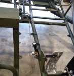
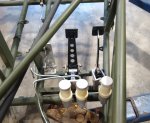
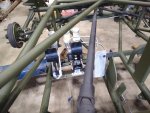
Well I got the pedals finished today, with 3 brand new Wilwood master cylinders, all of the originals were 5/8 which is OK from a parts inventory point of view but the 5/8" is a little too small for the clutch, would make the pedal lighter but requires more throw, so I replaced the clutch master cylinder with a 3/4" unit.
IMG_20221203_134838980.jpg
I had installed a rear brake proportioning valve but that was before I fully understood the brains behind the Neil pedals, the brake bias can be adjusted at the pedal, genius!

So I removed the manual valve and re-plumbed the brake lines.
IMG_20221203_145818105.jpg

I am still looking for pedal pads to fit the Neil pedals, it seems they would be sized for an available pedal pad rather than having to produce their own.
IMG_20221203_145847316.jpg
Now on to the transmission...
 

Mogman

Moderator
Staff member
Moderator
Steel Soldiers Supporter
6,945
9,606
113
Location
Papalote, TX
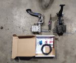
Interestingly today at a local hot rod shop selloff I picked up this lot, the pedals and the slave cylinder are pretty much exact copies of the much earlier Neil components.
The pedals are cast aluminum and there has been some refinement but basically same poop different cat box.
The NOS in the box is a remote adjustment kit so you can dial in the adjustable brake bias on the fly, would work perfectly on the Neil pedals.
The thought is maybe I can just set it up temporarily and just make the adjustment permanent after dial it in as installing it would be a little out of bounds IMHO.
Not too bad for $60 total..
IMG_20221203_174528090.jpg
 
Top
AdBlock Detected

We get it, advertisements are annoying!

Sure, ad-blocking software does a great job at blocking ads, but it also blocks useful features of our website like our supporting vendors. Their ads help keep Steel Soldiers going. Please consider disabling your ad blockers for the site. Thanks!

I've Disabled AdBlock
No Thanks