• Steel Soldiers now has a few new forums, read more about it at: New Munitions Forums!

  • Microsoft MSN, Live, Hotmail, Outlook email users may not be receiving emails. We are working to resolve this issue. Please add support@steelsoldiers.com to your trusted contacts.

Surplus Military Atlas Copco QAS38 Generator Issues

hawk-aggie

Member
79
50
18
Location
College Station, Texas
First off, I have a couple of manuals for this unit. One is the Service Manual for the engine. The other is the instruction manual for the generator. I have been unsuccessful in locating any TMs.

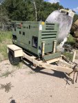
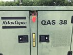
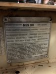
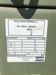
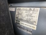
We have a surplus military Atlas Copco QAS38 YdS TNV 33.3Kw generator. It does not start with a conventional ignition switch. It has an electronic start sequence - flip the main switch, it goes through a pre-heat process, then it's supposed to crank the engine and start. Here's what I've got.

It has new oil and filters.
It has new fuel filters.
It has fuel.
The fuel system has been primed via the hand pump on the fuel injector pump.
It has 2 12v batteries connected in parallel. Voltage is 12.55vdc.
It has 2 starter relays in the circuit. Voltage at both relays is 12.55vdc.
Voltage at starter is 12.55vdc. No, I have not jumped the starter to see if the engine will turn over.
Voltage at alternator is 12vdc.
There is DC power to the starter switch, which has 7 LEDs on it. LED 1 indicates that the electrical system of the engine is energized. It works - solid green. LED 2 indicates that the glow plugs are warming up. It works - flashes green. It should go out after about 10-12 seconds, but cycle 3 times, then goes out. LED 4 indicates that there is no AC input (< 75 V line-to-neutral) is present. It works - solid red. Those are the only 3 LEDs that work currently. [L3 is the alternating charging indicator. L5, L6 and L7 are overseen shutdown, coolant temperature fault and oil pressure fault indicators respectively. Would only know if L3 and L5-7 are working when the generator gets running.]
The 12vdc panel light does not come on when the light switch is on. The light bulb looks like a large tubular glass fuse. It has continuity.
There is a push button fuse/circuit breaker on the front of the control panel. Admittedly, I have not checked it for continuity, because I just thought of it as I'm writing this inquiry.
I have checked the Dip-switches on the back of the control panel and reset them as shown in the manual.
It did not come with a magnetic pickup. I bought a new one and installed it based on my experience with the MEP-type generators we have. I have not found any guidance on exact set up yet.


Also, there is an 8 or 6 gauge yellow/green cable that runs to the AC ground bus bar behind the control panel that was disconnected when we got the unit. Typically, yellow/green is an indication of an earth ground. Normally, I would say the yellow/green cable should be connected to the frame of the generator or the trailer, but there's no indication of where it might have been attached.

I have electrical schematics, but they are hard to follow from page to page. It's likely that I missed what I'm looking for, even after reviewing them more than a dozen times. When I do find something tat I want to go check, I've no roadmap to tell me where the part I want to check is located.

Here's the punch line. I've been working on this thing off and on for nearly a year. I need a reset. Give me some tips regarding where to start diagnosing the start sequence.
 

Guyfang

Moderator
Staff member
Moderator
16,413
23,349
113
Location
Burgkunstadt, Germany
Post some pictures. I would like to see it. I was just on the Graf Kasserne, and cruzing the motor pools. If I can see what it looks like, I might be able to get someone to talk about it. And some shots of the Data plates?
 

hawk-aggie

Member
79
50
18
Location
College Station, Texas
If my photos come through, they are the best I can do at this time. I don't have any photos of the inside and won't be able to get them soon. I'm grounded after foot surgery and have another surgery in 8 days.
 

Attachments

2Pbfeet

Well-known member
355
629
93
Location
Mt. Hamilton, CA
@hawk-aggie I know nothing. Dumb question here, but given the military predilection for 24V, what are the chances that your unit was modified to 24V, rather than 12V? E.g. does the alternator data plate read 24V, or 12V, or perhaps a schematic that shows whether the batteries are wired in series rather than parallel? I'm not suggesting trying 24V unless you can find support for 24V!

Good luck on the foot surgery.

All the best,

2Pbfeet
 

hawk-aggie

Member
79
50
18
Location
College Station, Texas
System is 12V. check

check DIP Switches Dip switches set as indicated on page 11, paragraph 2.7, of the Instruction Manual. Are the dip switch settings indicated on page 11 only correct for when a remote start module is connected? If so, what would be the dip switch settings for "manual" start? and reset oil pressure switch as per manual. Makes sense. I have not found the reset process for the oil pressure switch. In which manual is that located?

Wiring Diagram starts at page 25. Ok, I've been reviewing it time and time again over many months. Is there something specific I should be looking for?

They are normally started through remote start switch, not the front panel. Good to know, but that doesn't help at the moment. The unit didn't have the remote starter when we got it. - still don't have one. So, I'm restricted to using the front panel, which is showing select signs of 12V power.

Is there any instruction on how to set/adjust the magnetic pickup?

On page 9 of the manual it reads, "Panel light H1 lights up as soon as the starter switch is turned into position (start), indicating that the fuel solenoid is energized." The panel light on our unit doesn't do that. If the light bulb is good, I would then assume that the fuel solenoid is NOT energized.


Good info. Please keep it coming. Thanks!
 

peapvp

Well-known member
Steel Soldiers Supporter
1,079
1,156
113
Location
Basehor, KS
First question:

Does the unit crank when it comes out of preheat?

Answers:
This is the only DIP Switch settings you should use as in Paragraph 2.7

The Oil Pressure Reset is done every time the ST Switch is moved from either Start / Remote Start Position to the 0 Position


The state of Q1.1 or Q1.2 is important and requires to be set correctly prior to starting and depends on if manual or remote start is used:

3.3 Before starting
– With the generator standing level, check the engine oil level and top up if necessary. The oil level must be near to, but not exceed the high mark on the engine oil level dipstick.
– Check the coolant level in the expansion tank of the engine cooling system. The water level must be near to the FULL mark. Add coolant if necessary.
– Drain any water and sediment from the fuel pre-filter. Check the fuel level and top up if necessary. It is recommended to fill the tank after the day’s operation to prevent watervapor in a nearly empty tank from condensing.
– Check the vacuum indicator of the air filter. If the red part shows completely, replace the filter element.
– Press the vacuator valve of the air filter to remove dust.
– Check the generator for leakage, tightness of wire terminals, etc. Correct if necessary.
– Check that fuse F4 is not activated and that the emergency stop is in the “OUT” position.
– Check that the load is switched off.
– Check that circuit breakers Q1.1 and Q1.2 are switched off.
– Check the correct position of the voltage selector switch (S10) on the alternator.


The Start Sequence as follows:

3.4 Starting
To start up the unit locally, without using the remote start/stop switch, proceed as follows:
– Put the starter switch in position "Normal Start" . The unit starts a preheating cycle which takes 12 seconds.
After the preheating period, the unit will start. The starting attempt will take maximum 12 seconds. If the unit does not start immediately, it will perform another two starting attempts.
– Approximately 15 seconds after starting (stabilization time for the generator), the timer relay closes the voltage free contact and the plant contactor is energized (if installed).
– Check that the warning lamps on the control and indicator panel are out. Refer to “Control and indicator panel” for component locations.
– Run the engine for approximately 5 minutes to warm up.
– Check the engine oil pressure (P9) and the cooling water temperature (P8).
– Check the voltmeter P4 (with voltmeter selector switch S4 in different positions) and the frequency meter P5.
Switch on circuit breaker Q1.1 or Q1.2, depending on the mode the generator is running in.
– Switch on the load and check the ammeters P1, P2 and P3, voltmeter P4 (voltmeter selector switch S4 in different positions) and the frequency meter P5.

To start up the unit from a remote location using the remote start/stop switch, proceed as follows:
– Put the starter switch in position "Remote Start".
– Switch on circuit breakers Q1.1 or Q1.2, depending on the mode the unit is running in.
– Put the remote start/stop switch in position start. The unit starts a preheating cycle which takes 12 seconds.
– After the preheating period, the unit will start. The starting attempt will take maximum 12 seconds.
– Approximately 15 seconds after starting (stabilization time for the generator), the timer relay closes the voltage free contact and the plant contactor is energized (if installed).
– Check that the warning lamps on the control and indicator panel are out. Refer to “Control and indicator panel” for component locations.
– Run the engine for approximately 5 minutes to warm up.
– Check the engine oil pressure (P9) and the cooling water temperature (P8).
– Check the voltmeter P4 (with voltmeter selector switch S4 in different positions) and the frequency meter P5.
– Switch on the load and check the ammeters P1, P2 and P3, voltmeter P4 (voltmeter selector switch S4 in different positions) and the frequency meter P5.


Follow the above Sequence(s) to the dot. If your unit does not crank, then you need to go through the troubleshoot part of manual
 
Last edited:

hawk-aggie

Member
79
50
18
Location
College Station, Texas
My responses in blue below (we're running out of colors)
First question:

Does the unit crank when it comes out of preheat? Nope, the process doesn't get past the glow plug pre-heat cycle.

Answers:
This is the only DIP Switch settings you should use as in Paragraph 2.7. Check - they were set as the manual indicates when we received the unit, but they are now.

The Oil Pressure Reset is done every time the ST Switch is moved from either Start / Remote Start Position to the 0 Position. Check


The state of Q1.1 or Q1.2 is important and requires to be set correctly prior to starting and depends on if manual or remote start is used:

3.3 Before starting
– With the generator standing level, check the engine oil level and top up if necessary. The oil level must be near to, but not exceed the high mark on the engine oil level dipstick. Check - oil is new
– Check the coolant level in the expansion tank of the engine cooling system. The water level must be near to the FULL mark. Add coolant if necessary. Check - coolant is new
– Drain any water and sediment from the fuel pre-filter. Check the fuel level and top up if necessary. It is recommended to fill the tank after the day’s operation to prevent water vapor in a nearly empty tank from condensing. Check - filters and fuel are new
– Check the vacuum indicator of the air filter. If the red part shows completely, replace the filter element. Check - filters are new
– Press the vacuator valve of the air filter to remove dust. Check - clean
– Check the generator for leakage, tightness of wire terminals, etc. Correct if necessary. Leakage? Appears all connections are good
– Check that fuse F4 is not activated and that the emergency stop is in the “OUT” position. Need to check F4 again to confirm. Emergency Stop button is "OUT"
– Check that the load is switched off. Check - since it's never ran yet, no load has ever been connected.
– Check that circuit breakers Q1.1 and Q1.2 are switched off. Check - they've never been turned on
– Check the correct position of the voltage selector switch (S10) on the alternator. Will do - didn't know it had a selector switch. Is the switch actually on the alternator? I've not found any indicator in the manual that there's a selector switch. That's probably only important when I get the engine running.


The Start Sequence as follows: I have read and reread this procedure several times to insure that I was doing things correctly.

3.4 Starting
To start up the unit locally, without using the remote start/stop switch, proceed as follows:
– Put the starter switch in position "Normal Start" . The unit starts a preheating cycle which takes 12 seconds.
After the preheating period, the unit will start. The starting attempt will take maximum 12 seconds. If the unit does not start immediately, it will perform another two starting attempts. This is as far as it gets, and L4 LED illuminates red. The engine DOES NOT try to start.
– Approximately 15 seconds after starting (stabilization time for the generator), the timer relay closes the voltage free contact and the plant contactor is energized (if installed).
– Check that the warning lamps on the control and indicator panel are out. Refer to “Control and indicator panel” for component locations.
– Run the engine for approximately 5 minutes to warm up.
– Check the engine oil pressure (P9) and the cooling water temperature (P8).
– Check the voltmeter P4 (with voltmeter selector switch S4 in different positions) and the frequency meter P5.
Switch on circuit breaker Q1.1 or Q1.2, depending on the mode the generator is running in.
– Switch on the load and check the ammeters P1, P2 and P3, voltmeter P4 (voltmeter selector switch S4 in different positions) and the frequency meter P5.

To start up the unit from a remote location using the remote start/stop switch, proceed as follows:
– Put the starter switch in position "Remote Start".
– Switch on circuit breakers Q1.1 or Q1.2, depending on the mode the unit is running in.
– Put the remote start/stop switch in position start. The unit starts a preheating cycle which takes 12 seconds.
– After the preheating period, the unit will start. The starting attempt will take maximum 12 seconds.
– Approximately 15 seconds after starting (stabilization time for the generator), the timer relay closes the voltage free contact and the plant contactor is energized (if installed).
– Check that the warning lamps on the control and indicator panel are out. Refer to “Control and indicator panel” for component locations.
– Run the engine for approximately 5 minutes to warm up.
– Check the engine oil pressure (P9) and the cooling water temperature (P8).
– Check the voltmeter P4 (with voltmeter selector switch S4 in different positions) and the frequency meter P5.
– Switch on the load and check the ammeters P1, P2 and P3, voltmeter P4 (voltmeter selector switch S4 in different positions) and the frequency meter P5.


Follow the above Sequence(s) to the dot. If your unit does not crank, then you need to go through the troubleshoot part of manual
Thanks. I have reviewed paragraph 6.5 Engine Trouble Shooting several times. Most of the faults apply to an engine that shows signs of trying to start. Something (a relay, broken wire, fuse) is preventing "a start the engine" signal from being sent from the control panel.

I may jump across the starter to see if the engine will react.

*****QUESTION*****. Do you know where the large gauge yellow/green cable inside the engine compartment connects?
Supposedly, that cable is an "earth" ground. I assume that it should be connected to the generator or trailer frame at a location that can have access to grounding.
 

peapvp

Well-known member
Steel Soldiers Supporter
1,079
1,156
113
Location
Basehor, KS
My responses in blue below (we're running out of colors)
First question:

Does the unit crank when it comes out of preheat? Nope, the process doesn't get past the glow plug pre-heat cycle.

Answers:
This is the only DIP Switch settings you should use as in Paragraph 2.7. Check - they were set as the manual indicates when we received the unit, but they are now.

The Oil Pressure Reset is done every time the ST Switch is moved from either Start / Remote Start Position to the 0 Position. Check


The state of Q1.1 or Q1.2 is important and requires to be set correctly prior to starting and depends on if manual or remote start is used:

3.3 Before starting
– With the generator standing level, check the engine oil level and top up if necessary. The oil level must be near to, but not exceed the high mark on the engine oil level dipstick. Check - oil is new
– Check the coolant level in the expansion tank of the engine cooling system. The water level must be near to the FULL mark. Add coolant if necessary. Check - coolant is new
– Drain any water and sediment from the fuel pre-filter. Check the fuel level and top up if necessary. It is recommended to fill the tank after the day’s operation to prevent water vapor in a nearly empty tank from condensing. Check - filters and fuel are new
– Check the vacuum indicator of the air filter. If the red part shows completely, replace the filter element. Check - filters are new
– Press the vacuator valve of the air filter to remove dust. Check - clean
– Check the generator for leakage, tightness of wire terminals, etc. Correct if necessary. Leakage? Appears all connections are good
– Check that fuse F4 is not activated and that the emergency stop is in the “OUT” position. Need to check F4 again to confirm. Emergency Stop button is "OUT"
– Check that the load is switched off. Check - since it's never ran yet, no load has ever been connected.
– Check that circuit breakers Q1.1 and Q1.2 are switched off. Check - they've never been turned on
– Check the correct position of the voltage selector switch (S10) on the alternator. Will do - didn't know it had a selector switch. Is the switch actually on the alternator? I've not found any indicator in the manual that there's a selector switch. That's probably only important when I get the engine running.


The Start Sequence as follows: I have read and reread this procedure several times to insure that I was doing things correctly.

3.4 Starting
To start up the unit locally, without using the remote start/stop switch, proceed as follows:
– Put the starter switch in position "Normal Start" . The unit starts a preheating cycle which takes 12 seconds.
After the preheating period, the unit will start. The starting attempt will take maximum 12 seconds. If the unit does not start immediately, it will perform another two starting attempts. This is as far as it gets, and L4 LED illuminates red. The engine DOES NOT try to start.
– Approximately 15 seconds after starting (stabilization time for the generator), the timer relay closes the voltage free contact and the plant contactor is energized (if installed).
– Check that the warning lamps on the control and indicator panel are out. Refer to “Control and indicator panel” for component locations.
– Run the engine for approximately 5 minutes to warm up.
– Check the engine oil pressure (P9) and the cooling water temperature (P8).
– Check the voltmeter P4 (with voltmeter selector switch S4 in different positions) and the frequency meter P5.
Switch on circuit breaker Q1.1 or Q1.2, depending on the mode the generator is running in.
– Switch on the load and check the ammeters P1, P2 and P3, voltmeter P4 (voltmeter selector switch S4 in different positions) and the frequency meter P5.

To start up the unit from a remote location using the remote start/stop switch, proceed as follows:
– Put the starter switch in position "Remote Start".
– Switch on circuit breakers Q1.1 or Q1.2, depending on the mode the unit is running in.
– Put the remote start/stop switch in position start. The unit starts a preheating cycle which takes 12 seconds.
– After the preheating period, the unit will start. The starting attempt will take maximum 12 seconds.
– Approximately 15 seconds after starting (stabilization time for the generator), the timer relay closes the voltage free contact and the plant contactor is energized (if installed).
– Check that the warning lamps on the control and indicator panel are out. Refer to “Control and indicator panel” for component locations.
– Run the engine for approximately 5 minutes to warm up.
– Check the engine oil pressure (P9) and the cooling water temperature (P8).
– Check the voltmeter P4 (with voltmeter selector switch S4 in different positions) and the frequency meter P5.
– Switch on the load and check the ammeters P1, P2 and P3, voltmeter P4 (voltmeter selector switch S4 in different positions) and the frequency meter P5.


Follow the above Sequence(s) to the dot. If your unit does not crank, then you need to go through the troubleshoot part of manual
Thanks. I have reviewed paragraph 6.5 Engine Trouble Shooting several times. Most of the faults apply to an engine that shows signs of trying to start. Something (a relay, broken wire, fuse) is preventing "a start the engine" signal from being sent from the control panel.

I may jump across the starter to see if the engine will react.

*****QUESTION*****. Do you know where the large gauge yellow/green cable inside the engine compartment connects?
Supposedly, that cable is an "earth" ground. I assume that it should be connected to the generator or trailer frame at a location that can have access to grounding.
I am going to answer last question about green/yellow wire first.

green or green/yellow is always protective earth ground

my guess would be that this wire is currently connected to the generator frame.

Based on this guess, as it would be logic, then this wire would connect to a ground rod, which has to be hammered into the ground / soil next to where the Genset is supposed to be operated

check the manual for the ground rod storage location within generator for / during transport


As to the no crank situation:

The LED 4 turns red because the rpm sensor is not sensing any rpm because the starter is not cranking

tap the starter lightly with a hammer before trying the next start, since you stated you had 12V all the way to starter.
Sometimes they get stuck because of sitting for ages
Sometimes the relay on starter has corroded contacts
 

hawk-aggie

Member
79
50
18
Location
College Station, Texas
I am going to answer last question about green/yellow wire first.

green or green/yellow is always protective earth ground

my guess would be that this wire is currently connected to the generator frame.

Based on this guess, as it would be logic, then this wire would connect to a ground rod, which has to be hammered into the ground / soil next to where the Genset is supposed to be operated

check the manual for the ground rod storage location within generator for / during transport


As to the no crank situation:

The LED 4 turns red because the rpm sensor is not sensing any rpm because the starter is not cranking

tap the starter lightly with a hammer before trying the next start, since you stated you had 12V all the way to starter. Old School - I like it.
Sometimes they get stuck because of sitting for ages
Sometimes the relay on starter has corroded contacts
Thanks again. I ask about the yellow/green cable because it wasn't connected to anything, and it's still not. I didn't just want to randomly "ground" it somewhere. There is a "Ground" lug (labeled as such) on the generator frame (not the trailer frame), but the cable is not long enough to reach. I will likely improvise and make a ground connection on the opposite side of the generator frame, that's within reach of the cable. There is also a ground lug on the trailer frame where a connection would be made to a grounding rod. That ground lug is also too far away to connect the yellow/green cable. There is no storage that I can find for a ground rod. In fact, there's no such storage at all.

Would you have any details regarding setting/adjusting the magnetic pick up? The original one was missing when we got the unit. I bought a new one, and it's installed as I would have installed it in an MEP 804.
 

peapvp

Well-known member
Steel Soldiers Supporter
1,079
1,156
113
Location
Basehor, KS
Here is a short explanation of the wiring diagram. They conform to DIN / IEC which is primarily used in Europe

The small cap letter and number next to each wire indicates gauge in square millimeter and color

IMG_1161.png

then the wiring scheme itself is more or less self explanatory

IMG_1162.jpeg

the starter is activated on the control module X16 terminal 2 which connects with wire b3 1.5 mm2 orange to K5 through connector x10 terminal A3 (check connector)

K5 switches then K0 (starter solenoid) which is wire c2 2.5 mm2 red

Main cable for 12V to starter is j0 50 mm2 black which should have 12V as soon as battery is connected with plus and minus

start the system with ST in Normal and check x16 terminal 2 for 12 V follow the money to starter
Should come on as soon as preheat times out

L4 will turn off as soon as engine cranks and fires up and voltage regulator starts exciting exciter coil

only at this point the rpm sensor becomes relevant

the rpm sensor will not block cranking

I probably should have explained this better earlier
 
Last edited:
Top