• Steel Soldiers now has a few new forums, read more about it at: New Munitions Forums!

  • Microsoft MSN, Live, Hotmail, Outlook email users may not be receiving emails. We are working to resolve this issue. Please add support@steelsoldiers.com to your trusted contacts.

Transfer case help….M1078 2001

AdiBarbu

New member
17
7
3
Location
BC , Canada
Is a rear wheel spinning? You only get 30% of the torque out the front if the center diff has something to push against. If a rear wheel is spinning under the conditions you describe, then 100% of the torque is escaping thru that spinning rear wheel. That is one reason for the standard 70/30 torque split typically found in AWD vehicles. It is easier to control a vehicle with a rear wheel spinning/sliding than a front…

park on ice, set the park brake and put it in drive and try again, that or jack up a front wheel and with the park brake set put it in drive. You should see 100% of the torque escape thru the front wheel that can slip or is lifted...
I put a front wheel on ice and rear with parking brake on and yes, it is spinning.
 

AdiBarbu

New member
17
7
3
Location
BC , Canada
I'm not following how the resistance could be *lower* measured through the harness versus directly at the solenoid. The wiring should not be able to lower the resistance reading.

And resistance measurements (with a DMM for example) are not really appropriate for measuring the circuit resistance since the extremely tiny current being produced by the meter isn't enough to really load the circuit so there's really two problems:

1. Circuit resistance CANNOT drop when adding wiring to a resistive load. Logically those readings HAVE to be wrong or those aren't actually the same circuit or something. I'm not familiar with the pinout of the A0 diagnostic port so I would have to look that up to verify but I suspect something is wrong with the test procedure.

2. DMM resistance measurements using it's built-in 9v source aren't appropriate for checking the circuit. Better to isolate the circuit and do a load test with a known resistive load like an incandescent bulb - a high beam headlight bulb @ 12v can pull about 4 amps. If the wiring can light a bulb brightly then it's likely ok. The DMM can't test the ability of the circuit to actually drive a load so any resistance measurements are basically useless.
I found a 12v incandescent bulb with a 3.3ohm resistance and hooked it in A and B ports in transfer case harness plug for solenoid. It is doing nothing and the transmission gives right away the 4523 code (missing solenoid). Does not want to take it. Also I can not read any voltage in there. I think once it detects failure, TCM stops sending signal? When I hook up again the harness, and press mode I can see that pulsations in front driveshaft.
So for any readings with oscilloscope, I have to have the solenoid plugged in.
I found a really cheap (20$) complete valve on e-bay and the vendor advertise it as new. At least will that will help me with troubleshooting.
cheers.
 

Ronmar

Well-known member
3,930
7,618
113
Location
Port angeles wa
Yes, you need to connect it to a low impedance load otherwise it will fault. Is your meter set for AC voltage? It is such a small voltage and duty cycle, it has almost no DC component to measure.

The supervisory/test signal is the same 7khz signal. i measured ~60millivolts AC initially. With a relay coil connected in place of the C7 solenoid down at the transfer case connector. Fault or not, i think you should always be able to measure that tiny signal as I believe it is always present so the TCU knows when the circuit is intact. It monitors that to determine circuit open and probably monitors current thru the circuit in operation to determine a short circuit.

You could also make up some jumper wires to connect between the harness connector and the transfer case connector and connect your meter to those wires to monitor the signal while the circuit is connected to the actual 3.6 ohm C7 solenoid coil. That should allow you to sample the signal without throwing a fault code.

if your meter can measure duty cycle, that 60 millivolt(0.06v signal) should be around 20% duty cycle(20% on).

When i select mode the signal jumps to around 15V AC @ 50% duty cycle briefly(3/4 second peak phase) and drops to around 11V AC @ 20% duty cycle to hold the solenoid closed with minimal current flow.
 
Last edited:

AdiBarbu

New member
17
7
3
Location
BC , Canada
Yes, you need to connect it to a low impedance load otherwise it will fault. Is your meter set for AC voltage? It is such a small voltage and duty cycle, it has almost no DC component to measure.

The supervisory/test signal is the same 7khz signal. i measured ~60millivolts AC initially. With a relay coil connected in place of the C7 solenoid down at the transfer case connector. Fault or not, i think you should always be able to measure that tiny signal as I believe it is always present so the TCU knows when the circuit is intact. It monitors that to determine circuit open and probably monitors current thru the circuit in operation to determine a short circuit.

You could also make up some jumper wires to connect between the harness connector and the transfer case connector and connect your meter to those wires to monitor the signal while the circuit is connected to the actual 3.6 ohm C7 solenoid coil. That should allow you to sample the signal without throwing a fault code.

if your meter can measure duty cycle, that 60 millivolt(0.06v signal) should be around 20% duty cycle(20% on).

When i select mode the signal jumps to around 15V AC @ 50% duty cycle briefly(3/4 second peak phase) and drops to around 11V AC @ 20% duty cycle to hold the solenoid closed with minimal current flow.
I was thinking the signal is DC, some square wave, from 0V to whatever 12v, and that gives % of duty cycle. I had no idea the signal is AC. I never set up the voltmeter below 20v DC and AC can measure only 200 and 300V, so no way to see anything. Looks like I have to invest in some more up to date gear. Also with all kind of home made jumpers, I am not sure that actually there is a good contact. I reach the conclusion that I waste my time (and yours) and I risk to make short circuit and brake something. I am shopping for some testing equipment to be able to work more safe precise.
BUT I still can see the front driveshaft trying to grab every turn when I press mode, so I broke nothing so far.
Also, when I took out the valve, I noticed 2 spools inside. One big and one small which I think acts as pressure regulator. I think The big spool is piloted by solenoid which allows (or not) a small flow to pass. Big spool has a spring and I could move it easily. I could not move at all the small spool with ease and I did not try to put more force, as it has no o-rings and all sealing is done thru precise machining. I was afraid not to indent the surface and ruin it. That small spool, may be jammed from sitting? I realized that is been a year since I did not engage mode. 2 years ago diff lock was working. I just watched a video of mine in deep snow and I could see all 4 wheels spinning. I will receive soon another Valve and I will be able to compare. Cheers!
 
Last edited:

GeneralDisorder

Well-known member
Steel Soldiers Supporter
2,121
5,401
113
Location
Portland, OR
It's not "AC" in the sense of a mechanically generated AC waveform that people think of when they think AC from the wall.

By switching the DMM over to AC coupling you are just telling it that it's looking at an oscillating signal and using various methods - RMS (Root Mean Squared) being the usual standard method of calculating a "voltage" from a signal where the voltage is changing essentially ALL the time. You can fool a meter into giving you a voltage reading from a PWM source that is switching on an off rapidly by using the AC coupling mode and also most meters have a duty cycle function that is attempting to display the frequency or percentage of on-time.....

A regular DMM is kindof inadequate though since you aren't getting all of the information. You can kinda guess through the muddy waters of a duty cycle reading and some voltage numbers that went through an RMS calculation designed for real AC waveforms rather than PWM but till you see the actual waveform on a scope and compare it to a known good - educated guessing is the best you can do.

Unplug the TCU from the harness, and unplug the solenoid and then check that the wires to the solenoid aren't shorted to ground or any of the other wires near them in the plugs/harness. Once you are satisfied that you have isolated the circuit wires, send 12v down them to a bulb and see if the circuit (both sides) can effectively carry enough current to brightly illuminate a halogen headlamp bulb that's around 3-4 amps. If it can't you know you have a harness problem. If it can, you know you have a TCU or solenoid problem.
 

AdiBarbu

New member
17
7
3
Location
BC , Canada
It's not "AC" in the sense of a mechanically generated AC waveform that people think of when they think AC from the wall.

By switching the DMM over to AC coupling you are just telling it that it's looking at an oscillating signal and using various methods - RMS (Root Mean Squared) being the usual standard method of calculating a "voltage" from a signal where the voltage is changing essentially ALL the time. You can fool a meter into giving you a voltage reading from a PWM source that is switching on an off rapidly by using the AC coupling mode and also most meters have a duty cycle function that is attempting to display the frequency or percentage of on-time.....

A regular DMM is kindof inadequate though since you aren't getting all of the information. You can kinda guess through the muddy waters of a duty cycle reading and some voltage numbers that went through an RMS calculation designed for real AC waveforms rather than PWM but till you see the actual waveform on a scope and compare it to a known good - educated guessing is the best you can do.

Unplug the TCU from the harness, and unplug the solenoid and then check that the wires to the solenoid aren't shorted to ground or any of the other wires near them in the plugs/harness. Once you are satisfied that you have isolated the circuit wires, send 12v down them to a bulb and see if the circuit (both sides) can effectively carry enough current to brightly illuminate a halogen headlamp bulb that's around 3-4 amps. If it can't you know you have a harness problem. If it can, you know you have a TCU or solenoid problem.
So maybe the TCU is reading impedance rather than resistance ?
I will definitely do the bulb test tomorrow!
I have a dielectric grease spray. Do you consider a good idea to spray contacts with that or not?
 
Last edited:

Ronmar

Well-known member
3,930
7,618
113
Location
Port angeles wa
It is a DC signal. The supervisory signal is so low it has very little DC component to measure with a digital multimeter. it shows better as an AC signal On a meter, but you will see it as square wave pulsed DC on an oscope… The DMM is Not useful for absolute measurements in this situation, but it is useful for observing changes of state like from supervisory to peak to hold and back to supervisory.
 

GeneralDisorder

Well-known member
Steel Soldiers Supporter
2,121
5,401
113
Location
Portland, OR
So maybe the TCU is reading impedance rather than resistance ?
I will definitely do the bulb test tomorrow!
I have a dielectric grease spray. Do you consider a good idea to spray contacts with that or not?
Dielectric greases are great for keeping contaminates out, but less than ideal to promote good contact. They usually aren't a *problem* and usually do more good than harm but occasionally someone will report issues.... They are non-conductive so they don't help the connection they just keep out moisture and oxygen..... but if you really want to be high speed then you use dielectric grease to seal the connector, and a product like Deoxit for cleaning, protecting, and promoting good conductivity on the actual pins and sockets. This is the one I use:


Just don't get it on the connector seals if you can help it - the carrier oil that's in it can cause the seals on weatherproof connectors to swell up. Deoxit makes this type of bottle for pin-point application accuracy if you just want to do the pins and sockets and then use dielectric grease on the connector seals:

 
Last edited:

AdiBarbu

New member
17
7
3
Location
BC , Canada
looks like you took a wrong turn somewhere… Lets start with the first pic. That large connector just inside the drivers door is the STE connector, stands for Standardized Test Equipment. It has NO connections whatsoever to the transmission wiring! The two pins you circled in white(P and S) connect to the starter and to the aux start solenoid respectively. Their intent was to either monitor the function of those components or allow control of them with a special test box plugged to that connector. STE really does not do much and any basically competent tech would quickly outgrow it. You can remove that connector, and the two black boxes just forward of it. They connect into the main truck wiring with 2 connectors tucked up into the dash. I can send you a pic later, pulled mine off years ago, and have re-used some of its wiring for other purposes…

The second pic, wire 125 has nothing to do with C7. In fact, unless you have a 6 wheel truck(3 axles) it is not even used.
A whole sequence happens when you go into 4X4

1. On the A0 you press mode, the trans controller, TCU selects a 5th gear preselect limit and the TCU outputs a mode indicator signal to the VIM on wire 114.
2. 114 energizes SF01 in the VIM.
3. SF01 in the VIM connects WIRE 161 and 163 sending a 4x4 request to the TCU which engages C7 to go from AWD to 4X4.
4. in 4X4 the TCU outputs a 4X4 indicator signal on wire 125 Back to the VIM. They programmed the TCU so that signal is reverse logic, so that 4X4 indicator signal actually de-energizes relay SF04 in the vim.
5. SF-04 in the vim is used to control 24v to an air solenoid under the passenger dash placed alongside the fan control air solenoid. That air feeds down to the rear middle axle on a 6X truck to lock up another center differential called a power divider so y0u can get torque applied to all 3 axles for maximum pull

there are no places in the transmission wiring to “sample” any of the transmission solenoid signals.

On the A0, the TCU in the drivers dash has 2 plugs on the back of it. One cable runs to the VIM, the other cable runs down to the transmission.

the cable running down to the transmission has an intermediary connector thru the front of the engine tunnel just forward of the gas pedal. You can reach it by removing the grill. That cable has some small branches that run to the front input speed sensor and also down to the C7/output speed connector on the transfer case, with the main branch of the cable ending at a connector down on the passenger side of the transmission above the valve body…
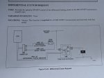
Ron,I look over the digram in the attached picture: I see solenoid hooked up to D1 and to the ground so I if I hook up a wire to D1 and another one to the ground, in my understanding I should have an appropriate signal. What I miss?
Thank you.
 

Attachments

GeneralDisorder

Well-known member
Steel Soldiers Supporter
2,121
5,401
113
Location
Portland, OR
That is just the request circuit and the indicator lamp circuit. The clutch pack solenoid is not in that diagram. I think you are mistaking the "Diff Clutch" item as a solenoid, but the wiring to that device says "Differential Clutch Indicator" *- which I'm not sure if that is optional and our trucks don't use it or if that's actually the MODE lamp on the button panel...... :unsure:. The lines radiating out from the "Diff Clutch" block are sort of a universal "lamp" diagram notation.

Also that can't be the solenoid since it's being fed ignition switched power and we know the solenoid is PWM.
 
Last edited:

AdiBarbu

New member
17
7
3
Location
BC , Canada
That is just the request circuit and the indicator lamp circuit. The clutch pack solenoid is not in that diagram. I think you are mistaking the "Diff Clutch" item as a solenoid, but the wiring to that device says "Differential Clutch Indicator" *- which I'm not sure if that is optional and our trucks don't use it or if that's actually the MODE lamp on the button panel...... :unsure:. The lines radiating out from the "Diff Clutch" block are sort of a universal "lamp" diagram notation.

Also that can't be the solenoid since it's being fed ignition switched power and we know the solenoid is PWM.
I miss the knowledge to differentiate a coil from a lamp haha and some more. Thanks.
 

Ronmar

Well-known member
3,930
7,618
113
Location
Port angeles wa
Ron,I look over the digram in the attached picture: I see solenoid hooked up to D1 and to the ground so I if I hook up a wire to D1 and another one to the ground, in my understanding I should have an appropriate signal. What I miss?
Thank you.
D1 on the VIM? D1 is an output to the power divider air solenoid on a 3 axle truck. Grounding it will have no effect on the trans and will probably pop a circuit breaker(CB 21)…

to send a diff lock/4X4 request it needs to be a signal ground from within the trans wiring system. Truck ground can actually be floating at a low voltage that might confuse a logic level sensing circuit, it even calls wire 161 a signal ground in the option programming diagram you provided from the troubleshooting manual. Relay SF 01 in the vim switches wire 161(signal ground) to wire 163(dif—lock request). The easiest way to produce this standalone diff lock request is to pull SF01 in the VIM and jumper pin 30-87 in its socket.

i added a standalone 4x4 switch on my truck. Wires 161 & 163 run from the vim to the TCU in the drivers dash. I found them there and ran them to a dash 4x4 switch. The other side of the switch controls a dash indicator light To tell me I have 4X4 selected…
 
Last edited:

Ronmar

Well-known member
3,930
7,618
113
Location
Port angeles wa
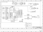
Here is a VIM diagram from the A0 schematic drawings. You have the A0 manuals right? A2 to A3 jumpered on the VIM, or SF01’s contacts, pin 30-87, will generate a transfer case diff-lock request to the TCU.

On the later WTEC 3 and 4 trucks(98+ A0 and A1) that don’t use the VIM they simply looped the mode indicator output signal(signal ground) right around into the diff lock req input line and skipped the external relay altogether…

IMG_4088.png
 

AdiBarbu

New member
17
7
3
Location
BC , Canada
D1 on the VIM? D1 is an output to the power divider air solenoid on a 3 axle truck. Grounding it will have no effect on the trans and will probably pop a circuit breaker(CB 21)…

to send a diff lock/4X4 request it needs to be a signal ground from within the trans wiring system. Truck ground can actually be floating at a low voltage that might confuse a logic level sensing circuit, it even calls wire 161 a signal ground in the option programming diagram you provided from the troubleshooting manual. Relay SF 01 in the vim switches wire 161(signal ground) to wire 163(dif—lock request). The easiest way to produce this standalone diff lock request is to pull SF01 in the VIM and jumper pin 30-87 in its socket.

i added a standalone 4x4 switch on my truck. Wires 161 & 163 run from the vim to the TCU in the drivers dash. I found them there and ran them to a dash 4x4 switch. The other side of the switch controls a dash indicator light To tell me I have 4X4 selected…
You explain this to me in a previous post but couldn't understand and make correlations because I was looking on wrong diagrams.
Now with the diagram you just posted makes more sense. Thank you.
I took for 4 years industrial electronics classes in college, but that was 10years ago and never used or practiced since. I worked as industrial mechanic and unions wouldn't allow cross trades, so I may be way wrong in the future, like I miss to make the difference between a coil and a lamp...Thank you for patience.
So By connecting wires 161 and 163 to a switch in the dash, you actually can have 4x4 in 7th gear, without having to press MODE?
 
Top
AdBlock Detected

We get it, advertisements are annoying!

Sure, ad-blocking software does a great job at blocking ads, but it also blocks useful features of our website like our supporting vendors. Their ads help keep Steel Soldiers going. Please consider disabling your ad blockers for the site. Thanks!

I've Disabled AdBlock
No Thanks