• Steel Soldiers now has a few new forums, read more about it at: New Munitions Forums!

  • Microsoft MSN, Live, Hotmail, Outlook email users may not be receiving emails. We are working to resolve this issue. Please add support@steelsoldiers.com to your trusted contacts.

Trick, functional jake brake grenade shifter

US6x4

Well-known member
Steel Soldiers Supporter
1,234
2,246
113
Location
Wenatchee, WA
One of my early deuces had an old dummy pineapple style grenade on the shifter.

It's all fun and games until you try to enter a military instillation.

Ask me how I know. o_O
Post 9-11, I assume? Did they want proof it was a dummy or ask for it to be removed? Was the guy with the rubber gloves extra thorough?
 

wreckerman893

Possum Connoisseur
15,629
2,054
113
Location
Akenback acres near Gadsden, AL
Let us say that the first guard that saw it had a low threshold for excitement. He had me empty my pockets and he started doing an extra through search of the cab while calling for a supervisor on his talkie. The sergeant that came out was an ex-military guy and knew it was a dummy. He strongly suggested that I remove it an put it in the OVM box while I was on base. I had tools so I took it off and stored it. Excitement over.
 

US6x4

Well-known member
Steel Soldiers Supporter
1,234
2,246
113
Location
Wenatchee, WA
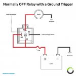
OK, now that my jake brakes have arrived I'm once again making forward progress on the wiring between the grenade and the brakes; particularly the relay that the grenade activates. I'm using a type 191 five prong 12 volt relay and wiring it to be ground triggered as shown in this diagram:
41oNhp7QX9L.jpg
The grenade is the ground trigger and the "device" will ultimately be the jake brakes via the rotary switch.

I picked up a heavy duty Bussman inline ATC fuse holder (15 amp fuse) and soldered it to the prestolite wire and to a 3/8" ring terminal to bolt to the 12V battery terminal.
20200312_090658.jpg
20200312_150130.jpg
20200312_154335.jpg

I ran the wire through the frame and up through the tranny tunnel cover alongside the speedo cable where it will mount to the relay which will be bolted to the top right heater diverter bolt. With the wires run, I hooked them up per the diagram.
20200312_135522.jpg
20200312_140056.jpg
20200312_143551.jpg

I hooked up the wire to the battery, stuck the test light in the relay blade and gave the grenade spoon a squeeze and what do you know? - It works! The blade that the test light is jabbed in will have a wire that goes to the clutch switch then the throttle switch and then back to the rotary switch.
20200313_162439.jpg
 

US6x4

Well-known member
Steel Soldiers Supporter
1,234
2,246
113
Location
Wenatchee, WA
The relay tucked up real nice between the heater duct hoses and the firewall. I removed a 1" knock out which is in the perfect place behind the rotary switch and just to the right of the jake heads where the wires will connect. It looks like the oil gauge supply line will have to move over to where X marks the spot.

20200315_095904.jpg 20200315_122351.jpg 20200315_103235.jpg 20200315_104011.jpg 20200315_122901.jpg
 

US6x4

Well-known member
Steel Soldiers Supporter
1,234
2,246
113
Location
Wenatchee, WA
More progress! Baby steps, but still progress. I got the oil line relocated which was involved and was something I've been not wanting to do. A 9/16" holesaw wobbled it's way to a perfect 5/8" hole and the hard line under the dash was soft enough to bend by hand to it's new shape. I was able to reuse the knockout that was formerly where the rotary switch is now to plug off the old oil line hole.

20200319_174712.jpg

This is the wiring pass through with the LO brake wire and the thermocouple wires (this will eventually be a different thread) sticking out.
20200319_174723.jpg


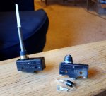
My clutch switch and throttle switch arrived today! These seem to be good quality switches and should work well. It pays to hunt these down from the source because truck suppliers sell them for 3x the price! I've designed the brackets for them already but still need to get them laser cut.
 

Attachments

Another Ahab

Well-known member
17,999
4,556
113
Location
Alexandria, VA
A 9/16" holesaw wobbled it's way to a perfect 5/8" hole and the hard line under the dash was soft enough to bend by hand to it's new shape.
It all looks great!

About that hole:

- Did you get lucky, or did you actually plan it that way?

(PS Lucky is ALWAYS good)
 

Jakelc15

Active member
718
37
28
Location
Hanover Pa
Looks great. I love having my switch on the shifter. Although I didn't get quite as fancy as you.
Those switches are the same type I used. They should hold up fine. Just keep something coated on the terminals. I like to use the battery terminal protector spray on most connections. Leaves a gel coating over open terminals. It also lubes the rubber shell connectors well.

I'm curious to see if your rear valve cover with the vent will rub the hood slightly like mine. Although I think my hood is bent, probably from too much foot traffic!
 

US6x4

Well-known member
Steel Soldiers Supporter
1,234
2,246
113
Location
Wenatchee, WA
I like to use the battery terminal protector spray on most connections. Leaves a gel coating over open terminals. It also lubes the rubber shell connectors well.

I'm curious to see if your rear valve cover with the vent will rub the hood slightly like mine. Although I think my hood is bent, probably from too much foot traffic!
That terminal spray is a good idea especially for the clutch switch which is in the wheel well - thanks for the tip.

The clearance with the hood will be interesting . Hopefully it all fits with no rubbing. I'm going to cover the actual jake head install in a new thread. This thread will just be my grenade shifter, controls, and wiring. Just waiting on 3 little seals from Cummins...
 
Last edited:

US6x4

Well-known member
Steel Soldiers Supporter
1,234
2,246
113
Location
Wenatchee, WA
I finished soldering the diodes in the wires for the HI setting last night (front & rear head wires get diodes, middle head is just a plain wire) and covered them up with wrong size heat shrink but I'll let it slide this time.
20200320_171618.jpg
20200320_172124.jpg

This morning I attached the 5 legged spider looking harness to the back of the water temp gauge stud with a coupler nut that replaces the regular nut on the back of the gauge just like elsewhere in the dash harness.
Now the 3 HI wires and 1 LO wire are connected and run out into the engine bay.
Yet to do is mount the throttle & clutch switches then run wire from the relay to the inline switches and then back to the rotary switch.
20200321_110013.jpg
20200321_110030.jpg
 

Another Ahab

Well-known member
17,999
4,556
113
Location
Alexandria, VA
I finished soldering the diodes in the wires for the HI setting last night (front & rear head wires get diodes, middle head is just a plain wire) and covered them up with wrong size heat shrink but I'll let it slide this time.
View attachment 793233
Your project looks great!

And about that wrong size heat shrink:

- Almost EVERY project takes a "sucker punch" of some kind somewhere in the details, no big deal, never sweat it.

Just write it off as the cost of doing business do-it-yourself style. You are doing something, THAT'S what counts

Cheers, Brother!!
 

US6x4

Well-known member
Steel Soldiers Supporter
1,234
2,246
113
Location
Wenatchee, WA
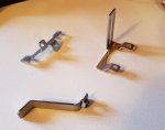
The switch brackets were laser cut out of 14 ga. stainless steel and formed up to the shapes you see.
20200401_203225.jpg
The welded 1/4" nut that's been drilled out on that Z bracket will index the bracket to the throttle lever just like the original throttle lever bolt so it should always stay straight.

20200401_120052.jpg


The hope for the bracket below is that it will piggy back over the high beam headlight switch and they will share a common fastener with no holes to drill. We will find out after the paint dries.
20200401_203159.jpg
20200401_120132.jpg
 

US6x4

Well-known member
Steel Soldiers Supporter
1,234
2,246
113
Location
Wenatchee, WA
Whoa...impressive.

That's some "fancy footwork" right there:

- How did you get all that done ("in-house", fabrication shop of some kind)?

yes, I have access to laser cutters, CNC press brakes, full machine shop, saw shop, tube benders, welders, hydraulic hose crimp machine, powder coating & wet paint shop, blasting booth...etc. Basically, everything you need to do this stuff the right way. All one needs is some imagination, time, and some play money :)
 

US6x4

Well-known member
Steel Soldiers Supporter
1,234
2,246
113
Location
Wenatchee, WA
The clutch switch bracket turned out better than expected - no grinding or tweaking required at all! It fit just right. I replaced the factory high beam light switch screws with 1" long button heads which provided enough extra screw threads on the backside to attach the bracket with nylocks. The switch has plenty of adjustment & attached with #6 screws.

20200403_170422.jpg
20200403_185628.jpg
20200403_181920.jpg
20200403_181930.jpg
20200403_184407.jpg
20200403_184436.jpg

The best part of this compact & sturdy bracket is that there are no holes to drill!
 

US6x4

Well-known member
Steel Soldiers Supporter
1,234
2,246
113
Location
Wenatchee, WA
I completed the wiring from the clutch switch to the throttle switch and back to the dash this morning. The dimmer switch screw is doing triple duty now since I added a p-clamp to it to hold the wires. The dimmer wiring p-clamp had enough extra room to add my two new wires to its bundle.
20200404_130037.jpg
20200404_130054.jpg

I added some rubber edging to prevent the wires from rubbing through on the inner fender panel.
20200404_130907.jpg

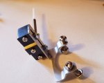
The throttle switch bracket went right on without a fuss as did the switch. The lever arm is little too long but it has been bent to work and the radius of the bend contacts the spherical end of the switch plunger so it seems to work ok.
20200404_100720.jpg
20200404_130123.jpg
20200404_130133.jpg

The only wiring left to do is from the fire wall to the jake heads. Stay tuned...
 

US6x4

Well-known member
Steel Soldiers Supporter
1,234
2,246
113
Location
Wenatchee, WA
I finished the wiring from the firewall to the jake heads today! I made some 10 ga. standoff brackets welded to 1/4" thick spacers to hold the wiring along 4 valve cover bolts and used flange head bolts to attach. Under the first bracket is a 3/4" and 5/16" p-clamps to hold the wye connector and a few wires. I trimmed some of the valve cover down to clear the brackets.
20200413_193728.jpg
20200413_193742.jpg
20200417_165222.jpg
20200417_171014.jpg
20200417_171947.jpg

I started with the middle head since it was only one wire and I used male connector rubber pieces to cover the connection simply to look like a military installed feature and it worked out perfect! The connector slides over the connector and fits snugly over the Jacobs pass-through fitting.
20200417_174414.jpg
20200417_174548.jpg

Same story for the double wires which shared a 10 ga. connector. I drilled out the hole in the rubber to accommodate two 14 ga. Prestolite wires.
20200417_180007.jpg
20200417_184256.jpg
20200417_184305.jpg
 
Top