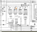
Well I was bored so I looked at the TM I directed to you and spotted a mistake in the truth tables
So lets look at how the switch works.
Pins
A Right front turn signal
B Left front turn signal
C Left rear turn signal/brake
D Brake light feed from light switch
E Right rear turn signal/brake light
F Power feed to turn signal flasher
G turn signal power feed from light switch
H feed from turn signal flasher to the directed turn lamps
So you will see than in the neutral position D, the brake light signal feeds C and E the rear turn signal/brake lights.
In any other position than neutral the power feed G from the light switch is connected to F the power feed to the flasher and the indicator light.
In the right position H, feed from the flasher is connected to A right front lamp and E right rear lamp, also D the stop light signal is connected to C the left rear stop/turn lamp and there is the error, there should not be a connection between the left rear stop/turn lamp and the right turn signal circuit as the arrow points to.
And for the left turn position H the feed from the turn signal flasher is connected to B the left front turn lamp and C the left rear turn/stop lamp, also D the brake light feed is connected to E the right rear turn signal/stop lamp.
I hope this helps...

I wonder who proof reads this stuff!!!!