HelluvaEngineer
Active member
- 191
- 82
- 28
- Location
- Atlanta, GA
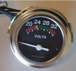
Hi everyone. My voltmeter died shortly after buying my m1009. Thanks for all who contributed helpful posts that came up on my search regarding debugging the voltmeter. I checked at the connections and I was getting 24v. So I pulled it. Then I took it to my shop and connected the 12v lug to my voltage supply. I came back to life. So it's safe to assume the resistor died. Looking at it closely it appears there should be copper contact points on the ends and they're no longer there.
I didn't have any 300 ohm resistors but I did have a pack of 150's. So I soldered two in series and gave it 24v. Now it's working great.
Since it was already connected to a variable voltage supply I ran a test to see the voltage required to hit each line on the meter. I also did a 24.0v test. I think the meter is pretty accurate! Anyway, maybe this will be helpful to someone in the future who's trying to debug their meter.
15.1v = Start of red (or some faded red-ish color)
18.9v = Start of yellow
22.2v = Start of green
24.0v = Middle of green
26.7v = Start of orange-ish color
32.1v = End of orange-ish color


