• Steel Soldiers now has a few new forums, read more about it at: New Munitions Forums!

  • Microsoft MSN, Live, Hotmail, Outlook email users may not be receiving emails. We are working to resolve this issue. Please add support@steelsoldiers.com to your trusted contacts.

What is the current draw of the glow plugs?

antennaclimber

Moderator
Moderator
Steel Soldiers Supporter
1,367
949
113
Location
State College, PA
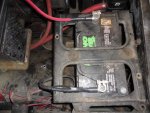
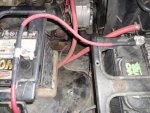
I finally found the ammeter pictures. Full scale is 50 amps on the meter.

One picture is the current draw for 4 glow plugs and the other is for 2 glow plugs. The pictures were taken after about 5-10 seconds of heating time.

This M1009 truck has the resistor by-pass modification.

Karl
 

Attachments

Last edited:

peapvp

Well-known member
Steel Soldiers Supporter
1,103
1,210
113
Location
Basehor, KS
Thank you Hasdrubal for posting the spec for the AC60G. I went by the published specs, which state that they are 200W at 10.5 Volts. Unfortunately, I cannot enlarge the spec4.jpg file enough to read the table.

As far as I know, all the old style "1 Minute Plug" have been phased out by the Military. All old NSN's for those Plugs are obsolete. They all were replaced by the 15 second "Fast Start Plug Type" for the specific equipment they are used in.

My question to antennaclimber is:

What was they actual Voltage applied to the DUT when you took the pictures of the Amp-meter?
 

antennaclimber

Moderator
Moderator
Steel Soldiers Supporter
1,367
949
113
Location
State College, PA
My question to antennaclimber is:

What was they actual Voltage applied to the DUT when you took the pictures of the Amp-meter?
That's a great question.

Unfortunately I no longer own that truck. But I do know that the batteries were good. So I would guess/estimate that the voltage was around 12.8 VDC.
I did not measure the voltage before, during or after the tests. I was just interested in current draw.

I may just re-run the tests again this weekend and measure the voltage and current during the GP cycle.
Karl
 

V8Astro

New member
118
1
0
Location
StL/MO
I'll amp clamp mine when I get home. I did the "12v bypass" and I will tell you that the 12v supply wire gets HOT while the GP's are on. I too have been thinking about running a heavier gauge cable for the 12v bus....
 

Hasdrubal

New member
690
4
0
Location
Vancouver BC
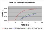
Wow, that chart is so small its unreadable. How can I re-size that so its at least legible? There are 4 charts altogether, if someones interested. Here's the amp vs time chart ;
 

Attachments

Zenk

Member
38
7
8
Location
VA
...
So, running that line over to the batteries requires fusing (or a circuit breaker), and inquiring minds want to know how to size it.
I am currently running direct to the battery without a fuse, what kind of trouble could this cause? It seems to me if you add a fusible link, you are taking away the advantages of running direct to the battery.
 

antennaclimber

Moderator
Moderator
Steel Soldiers Supporter
1,367
949
113
Location
State College, PA
I am currently running direct to the battery without a fuse, what kind of trouble could this cause? It seems to me if you add a fusible link, you are taking away the advantages of running direct to the battery.

This is on my list of electrical modifications to do as well.The only difference is that I am planning on adding a 125 to 150 amp circuit breaker or fuse. I will need to do a little more research on what my current demands will be.

Any additional wiring that is done in a vehicle needs to have a fuse, circuit breaker or other protection as close to the source as possible.
Otherwise you may have a catastrophic event.
The only exception I can think of is battery cables and high current leads between batteries and to the starter. These wires need to be protected and secured in their routing as well.

I have seen $1,000,000 pieces of machinery burn to the ground due to a simple clip lead and improper wiring. Just to power a simple CB radio.

High current wiring requires things to be 100% correct, do not take short cuts with it.
 

peapvp

Well-known member
Steel Soldiers Supporter
1,103
1,210
113
Location
Basehor, KS
The highest current which will flow, according to all the diagrams which have been posted here, is at the point of contact closure when the Relais is first activated.

This initial current is proportional to the cold resistance of the Glow Plug and the Voltage of the Battery. The Battery Voltage will most likely drop if there is a sufficient number of Plugs coming on simultaneous due to the high inrush current, caused by the low cold state resistance of the Plugs in question.

I would recommend a slow blow fuse type which will handle the to be expected in rush current sufficiently.

Most equipment I am familiar with ( all 24 VDC ) does not use any Fuses / Breakers for Glow Plugs whatsoever, but the currents in a 24 VDC System are basically half of that what you can expect in a 12 Volt System. Furthermore the Equipment I deal with utilizes 16 ga Airframe Wire Type II - which has a very high short term current rating and can handle inrush currents of several 100's of Amps with no problem.
 

MarcusOReallyus

Well-known member
4,524
816
113
Location
Virginia
I am currently running direct to the battery without a fuse, what kind of trouble could this cause?
A fire. It's that simple.

EVERY circuit should have protection (in theory). The only reason the high-current circuits (starter, main battery cables) don't have some kind of protection is $$$$. A circuit breaker or fuse sized for that kind of current would be a significant hit to the cost of each vehicle, and then opens up the need to replace them. So, weighing the costs against the benefits, instead of fusing them (in some way), the industry is just very careful to protect them to minimize the chance of short circuits.

Any time it's reasonably cost-effective to provide short-circuit protection, you should. For the glow plug circuit, it's a reasonable cost.

It seems to me if you add a fusible link, you are taking away the advantages of running direct to the battery.

Nope. Not at all. Not if it's sized correctly. OR do as antennaclimber suggests (which is my plan as well) and install a circuit breaker.

Sizing the wire and the circuit breaker is exactly why I asked this question.

I had no idea it was going to be this difficult to answer!
 

MarcusOReallyus

Well-known member
4,524
816
113
Location
Virginia
Furthermore the Equipment I deal with utilizes 16 ga Airframe Wire Type II - which has a very high short term current rating and can handle inrush currents of several 100's of Amps with no problem.

That's what it's all about - understanding the current requirements and choosing the correct conductor, both in terms of size and other characteristics. That's what makes those charts so valuable.

Using ordinary copper automotive wire, we'll need to go just a wee bit bigger than 16 gauge to handle the load safely. :mrgreen:


For myself, I plan to upgrade the individual feeder wires, too. Just up one gauge size, and of course, with the proper .250 terminals for the new plugs.
 

antennaclimber

Moderator
Moderator
Steel Soldiers Supporter
1,367
949
113
Location
State College, PA
I finally had time to measure the GP current and voltage today on a stock M1009 that has the standard resistor bypass procedure completed.


Test Set Up:
Cold engine approximately 58 degrees F.
4) AC60G glow plugs connected.
Resistor bypass procedure completed.
Installed ammeter inline at the feed to the top of the GP relay.


Current draw was the same as before, 50 amps then dropping to 35 amps approximately 20 seconds later just before the GP relay opened.
The ammeter only goes to 50 amps, so I can only test 4 at a time, double this amount with all 8 GP's connected.


Voltage at front battery posts was 11.6 volts with the GP relay closed.
Voltage at top of GP relay was 11.3 volts with the GP relay closed.
Voltage at GP connector was 11.28 volts with the GP relay closed.


With all 8 glow plugs connected one could expect more of a voltage sag at the relay and GP connectors.


I did upgrade the wiring on my other M1009 to help overcome the the voltage sag issues inherent to these vehicles.
Replaced compromised battery connectors, new battery wires, larger wire to the GP relay, head light relay upgrade and a heater fan relay upgrade.


The head light and heater fan relay modifications helped reduce the current draw through the headlight switch and the other modifications yielded a higher voltage to the GP's, starter motor and other electrical components.


Now if I could only get the the wipers to work on the high speed setting!
Karl
 

MarcusOReallyus

Well-known member
4,524
816
113
Location
Virginia
Good stuff, ac! Thanks very much. I'm sure this will be useful for lots of folks.


I'm going to be stubborn and run a separate lead for the GP system. Sounds like a 150 amp CB will do just fine. 120 should do, but I can't find any listings for that size.


Looking at various online ampacity tables, I'm getting different answers for cable size. Off the top of my head with no calculations, I was thinking something like 4 AWG would be plenty, but some tables are telling me I need to go up to 1 ga. That can't be right.


This one suggests I'll be fine with 4 AWG. But that's max current. Doesn't say anything about voltage drop.

Assuming a 6 foot length, this one tells me that 120 amps will give me a 2.4% voltage drop @ 90C in a 12v system using 2 AWG. That's certainly more than acceptable.


Actually, given the relatively short load duration, I think 4 ga. is plenty big, even overkill. Might drop down to 6.


What do you think?
 

antennaclimber

Moderator
Moderator
Steel Soldiers Supporter
1,367
949
113
Location
State College, PA
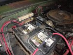
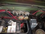
I used a piece of #2 from the batteries to a modified DC distribution block and then shortened the factory wire with the fusible link to the 12 volt junction near the GP relay. I moved the buss bar over one hole to allow for a 12 volt only stud, the rest of the bar is still 24 volts.

Eventually I will run a dedicated #4 from the DC distribution block directly to the GP relay with an inline 125 amp MAXI fuse.

The first picture is the heater fan relay modification prototype.
Karl
Blazer 3 028.jpgBlazer 3 024.jpgBlazer 3 023.jpgBlazer 3 020.jpgBlazer 3 025.jpg
 

Speddmon

Blind squirrel rehabiltator
Super Moderator
Steel Soldiers Supporter
4,640
28
38
Location
Cambridge, Ohio
For your wire you should easily be able to get by with a #4 or even smaller....yes I said smaller.

The big thing you need to remember with the ratings of the wire is that this application is what would be considered "in free air". Meaning the ambient air temp around the wire will dissipate the heat rather quickly. You also need to realize that the current is going to be there for such a short amount of time. And it is actually the insulation type that determines how much current you can pull through a wire and not so much the size of the copper conductor. The insulations have different temperature ratings...the higher the rating the more current a particular size conductor can handle. Even a #12 conductor can handle hundereds of amps if you can get the heat away from it fast enough so it doesn't melt itself or it's insulation.

For what it is worth, I ran a #4 "sil-a-blend" wire to my GP relay. It is an industrial wire insulation with a 150 or 200 degree C rating, so that particular #4 wire will never see enough current to damage it.
 
Last edited:

Speddmon

Blind squirrel rehabiltator
Super Moderator
Steel Soldiers Supporter
4,640
28
38
Location
Cambridge, Ohio
I'm at work and I just went to my wire room and pulled some sil-s-blend wire and looked. It is a 200 degree rated wire. And looking at the charts, 200 degree insulation on one conductor in free air with an ambient air temp of 40 degrees C (104 F) even a #8 wire has a current rating of 124 amps.
 

MarcusOReallyus

Well-known member
4,524
816
113
Location
Virginia
For your wire you should easily be able to get by with a #4 or even smaller....yes I said smaller.

The big thing you need to remember with the ratings of the wire is that this application is what would be considered "in free air". Meaning the ambient air temp around the wire will dissipate the heat rather quickly. You also need to realize that the current is going to be there for such a short amount of time.

Yep, that's why I was tossing around #6. But I just found a place online where I can order a 6 foot length of #4, with lugs and heat shrink, for 14 bucks. #6 only saves about 2 bucks. Whoop te do.

http://www.bestboatwire.com/custom-cables/custom-battery-cable-assembly


So, I think I'll go with the #4. A little overkill is a good thing.


AC, have you got a good source for the MaxiFuse? I'm finding them online, but only up to 80 amps. I see the MegaFuse or the ANL and AMG type at 100 and up all over, but not the Maxi. Well, except for one listing in Australia. :mrgreen:
 
Top
AdBlock Detected

We get it, advertisements are annoying!

Sure, ad-blocking software does a great job at blocking ads, but it also blocks useful features of our website like our supporting vendors. Their ads help keep Steel Soldiers going. Please consider disabling your ad blockers for the site. Thanks!

I've Disabled AdBlock
No Thanks