• Steel Soldiers now has a few new forums, read more about it at: New Munitions Forums!

  • Microsoft MSN, Live, Hotmail, Outlook email users may not be receiving emails. We are working to resolve this issue. Please add support@steelsoldiers.com to your trusted contacts.

wire numbers in a deuce

maddawg308

Well-known member
Steel Soldiers Supporter
10,865
762
113
Location
Appomattox, VA
Does someone have a list of all the wire numbers in a deuce? I am trying to decode some wire numbers that are causing routing problems in my truck, would like to know what the numbers are supposed to be used for.
 

GoHot229

Member
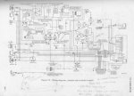
Go to www.olive-drab.com and in the upper right fill in 'search' box (m series circuit numbers) that will take you to a page and you will se exactly the site, hit that and scroll down. Theres all the #'s you will need.....Also, credit goes to 'Cranetruck' for the large scematic pic. It should be noted that all vehicles use the same numbering system with the tags
 

Attachments

Last edited:

Jones

Well-known member
2,237
83
48
Location
Sacramento, California
Mike,

The link 4052 put up is a good one; just click your way through and you'll see the number list as well as info on turn signal kit installs and the proper assy. of the waterproof connectors. Good stuff.
The beauty of the M-series vehicles is that they all use the same wire numbers. A number #15 (main light switch feed will be the same whether it's an M-151 or an M-813.
 

Numbers

New member
355
0
0
Location
near Ft. Knox
Good idea to use the schematic provided in conjunction with circuit number list.

ie... 100 amp alternator has at least one different number.

568, 1

654 is not labeled on circuit number pdf but is listed on the schematic.

Schematic Note: 654 and 28 are switched for the M-275A2

I am sure there are other examples. In other words use both.

TM 9-2320-361-24-1 (0011 00-1 thru 0015 00-14) and TM 9-2320-209-20-3 (FIG 435)
 

Scrounger

Active member
496
66
28
Location
Southern, Maryland
Wire Number
Circuit Description
1
Generator field circuit (main feed)
2
Generator armature circuit (main positive line)
3
Generator ground circuit
4
Generator regulator to ammeter or shunt
5
Ammeter or shunt to starter terminal block or battery connection
6
Battery to starter
7
Battery ground including master switch if in this circuit
8
Shunt to ammeter positive
9
Shunt to ammeter negative
10
Ammeter or shunt feed to instrument panel circuit breakers
11
Ignition switch feed or magneto ground (LH)
12
Ignition switch to ignition coil or booster switch to booster coil
13
Magneto ground (RH)
14
Starter switch circuit (including feed) to relay or solonoid
15
Main light switch feed
16
Light switch (HT) to service headlamp or dimmer switch
17
Dimmer switch to high beam service lamps
18
Dimmer switch to low beam service lamps
19
Light switch (BOD) to blackout driving lamp including resistor
20
Light switch (BHT) to blackout marker lamps
21
Light switch (HT) to service tail lamp
22
Light switch (S) to service stop lamp
22-460
Turn signal switch to right rear stop lamp
22-461
Turn signal switch to left rear stop lamp
23
Light switch (BS) to blackout stop lamp
24
Light switch (BHT) to blackout tail lamp
25
Horn switch (including feed) to horn or horn relay
26
Horn relay feed and horn relay to horn
27
Instruments feed (instruments with polarity)
28
Fuel indicator to sending unit if single tank, or left upper tank indicator to selector switch
29
Fuel selector switch to right upper tank
30
Fuel selector switch to left lower tank
31
Fuel selector switch to right lower tank
32
Oil level sending unit to indicator or selector switch
33
Water and oil temperature indicator to sending unit
34
Low engine oil pressure warning light circuit, including feed
35
High water temperature warning light circuit, including feed
36
Oil pressure indicator to sending unit
37
Outlet socket
38
Dome light circuit, including breaker and switch
39
Map light circuit
40
Instrument light circuit
41
Interphone #1
42
Interphone #2
43
Interphone #3
44
Interphone #4
45
Interphone #5
46
12 Volt radio circuit, including radio master switch
47
Slip ring feed
48
24 volt radio feed
49
Receptacle, aux power outlet, positive lead
50
Receptacle, aux power outlet, negative lead
51
Interphone #7
52
6 volt tap on tail light dropping resistor to tail light
53
Electric brake control circuit
54
Fuel cut-off circuit
55
Flame primer low tension circuit
56
Flame primer high tension circuit
57
Instrument panel ground
58
Compass light circuit
59
Hull ventilating fan circuit
60
Interphone #6 (extra)
61
Auxiliary generator field
62
Auxiliary generator armature (positive line)
63
Auxiliary generator ground
64
Auxiliary generator regulator to battery, including heater transfer switch
65
Auxiliary generator starter relay circuit, including switch and feed
66
Auxiliary generator starter to transfer switch, including starter or relay
67
Emergency stop switch ground
68
Battery interconnecting cables
69
Resistor to ground terminal on trailer coupling
70
Regulator ground (LH)
71
Windshield wiper circuit
72
Low transmission oil pressure indicator circuit, with feed (LH)
73
Radio terminal box to ground
74
Starter solonoid circuit (actuating) including switch or relay
75
Stop switch circuit (SW to SS on main light switch)
76
Fuel pump control feed
77
Fuel pump switch to fuel pump left
77B
Fuel pump safety cut-out switch (??)
78
Fuel pump switch to fuel pump right
79
Fuel tank ground
80
Ignition coil to distributor
81
Battery positive feed to starting motor terminal block, including master switch
82
Starter motor terminal block to starter motor, left
83
Main light switch (TT) to tail light connection on trailer receptacle
84
Main light switch (SS) to stop light connection on trailer receptacle
85
Low air pressure indicator light
86
Ground on series parallel switch, to ammeter, including circuit breaker
87
Spotlight circuit for trucks and wreckers
88
Winch torque limited control
89
Automatic choke
90
Trailer receptacle to ground
91
Headlamp to ground
92
Parking lamp to ground
93
Starter relay grounding circuit
94
Starter relay auxiliary grounding circuit
95
Tail lamp to ground
96
Speedometer sending unit feed
97
Tachometer sending unit feed
98
Interphone #8
99
Interphone #9

100
Turret feed
101
Impulse relay feed (L terminal on impulse relay)
102
Large cal. gun firing solenoid to impulse relay (S terminal)
103
Small cal. gun firing solenoid to firing switch
104
Traverse motor feed
105
Recoil circuit on gyro control, through recoil switch
106
Gyro control (#3 on an connector) to motor stabilizer control, yellow post
107
Gyro control (#1 on an connector) to motor stabilizer control, green post
108
Stiffness circuit including disengage switch
109
Gyro stab. switch feed including circuit breaker and switch to gyro motor or anti-backlash switch
110
Gun firing and lights, circuit breaker feed
111
Gun firing switch, feed from circuit breaker including safety switch
112
Gun firing safety switch indicator light
113
Firing switch to large gun firing solenoid or impulse relay (F terminal)
114
Gyro control resistors feed
115
Firing relay feed
116
Gyro indicator light feed
117
Positive lead to gun firing switches
119
Normally open side of anti-backlash switch, to circuit #107
120
Normally closed side of anti-backlash switch to gyro control resistors feed
121
Junction of circuits #114 and 120 to gyro motor feed
122
Firing switch to loaders safety relay
123
Loaders safety relay to shell primer
124
Firing switches to selector switch
125
Feed to loaders trip button
126
Loaders trip button to feed on test relay
127
Test relay to loaders safety relay coil
128
Loaders trip button through loaders setting button to controlled side of test relay
129
Loaders ready to fire indicator circuit
130
6.5 inch selector light
132
Ammunition hoist circuit
133
Parallel disconnect circuit
137
Outlet socket
138
Dome lamp, spot light and reel circuit
141
Interphone #1
142
Interphone #2
143
Interphone #3
144
Interphone #4
145
Interphone #5
146
12 Volt radio circuit
147
Light for periscope and sighting devices
148
24 Volt radio feed
149
Commanders master control circuit
151
Interphone #7
152
Commanders master control circuit feed
154
Rammer motor control circuit, including switch and indicator
155
Elevating motor feed through circuit breaker and main switch and indicator ligh
156
Brake solenoid feed through brake relay
157
Elevating lead from reversing relay to elevating depressing motor
158
Depressing lead from reversing relay to delevating depressing motor
159
Turret vent fan
160
Interphone #6 (extra when used)
161
Feed for elevating and depressing control mechanism through circuit breaker
162
Elevating relay control through control switch and limit switch
163
Depressing relay control through control switch and limit switch
164
Brake relay control through brake switch and ground
165
Elevating and depressing relay mechanism to ground
166
Automatic elevation control through resistor and limit switch
167
Automatic depressing control through resistor and limit switch
168
Equilibrator motor feed including switch and indicator light
169
Gun, How. firing area control circuit
173
Radio terminal box to ground
174
Rammer control circuit
198
Interphone #8
199
Interphone #9

201
Generator field circuit
202
Generator armature circuit
203
Generator ground circuit
204
Generator regulator to ammeter or shunt
211
Right hand ignition switch feed
212
Right hand ignition switch RH coil
214
Starter switch or relay feed circuit
233
Temperature gauge to sending unit
234
Oil pressure pilot light
235
Water temperature pilot light
236
Oil pressure gauge to sending unit
255
Flame primer low tension circuit
256
Flame primer high tension circuit
267
Emergency stop switch
270
Regulator ground right hand
272
Transmission oil pressure pilot circuit light
274
Starter solenoid circuit right
280
Ignition coil to distributor
282
Starter motor feed right hand
293
Starter relay grounding circuit
294
Starter relay auxiliary grounding circuit

300
Air pressure gauge to sending unit
301
Ignition switch to throttle solenoid through feed terminal in terminal box
302
Throttle solenoid to throttle out switch (H)
303
Throttle out switch to brake throttle switch (A)
304
Feed terminal in terminal box to feed on clutch switch (D) and normal range switch (E)
305
Normal range switch to low range (F) and high switches (G)
 

Scrounger

Active member
496
66
28
Location
Southern, Maryland
306
High range switch on low/high range shift to switch on high/normal range shift switch (K)
307
Switch on high/normal range feeding direct solenoid and converter solenoid
311
Brake governor switch (C) joining 312 to low side of governor
312
Convertor solenoid to brake governor switch (C)
313
Common lead on brake governor switches to high side of governor
314
Brake governor switch (B) to direct solenoid
315
Low range switch (F) on low/high range shift to high range solenoid
316
High range solenoid ground
317
Clutch switch (D) to clutch solenoid
318
Clutch solenoid to clutch solenoid ground switch (J) on converter direct shift
319
Common side of throttle cutoff switch and clutch grounding switch to grounding terminal on terminal box
320
Brake throttle switch to grounding terminal on terminal box
321
Transmission lube pressure gauge circuit
324
Transmission temperature gauge circuit
325
Red flasher light with switch indicator and flasher
326
Differential low oil pressure warning light
327
Transmission high oil temperature warning light
329
Feed to transmission and steering control
330
Transmission high range control
331
Transmission low range control
332
Transmission reverse range control
333
Transmission clutch lockup control
334
Steer control right
335
Steer control left
336
Converter low oil pressure
337
Pilot control indicator circuit
338
Co-pilot control indicator circuit
339
Converter low lubricating oil pressure
340
Speed selector switches feed, pilot
341
Steer selector switches feed, pilot
342
Speed selector switches feed, co-pilot
343
Steer selector switches feed, co-pilot
344
Inlet fan, right
345
Inlet fan, left
346
Circulating fan, right
347
Circulating fan, left

400
Heater feed
401
Heater starting switch to coil and indicator light
402
Heater starting switch to pump and solenoid valve
403
Running switch to thermal switch
404
Thermal switch to heater starting switch
405
Heater starting switch to motor and indicator light if used
406
Heater ignition circuit and indicator light if used
407
Heater in operating position indicator circuit
408
Oil heater circuit including indicator
409
Compartment heater circuit, including control unit
410
Safety valve reset circuit
411
Ventilation fan lead
412
Auxiliary generator transfer switch to battery heater and indicator
413
Heater relay control circuit
414
Auxiliary generator voltage control reostat to voltage regulator
415
Feed to special ventilating fan or rotoclone
416
Ground lead for special ventilating fan or rotoclone
417
Auxiliary shunt to auxiliary ammeter positive
418
Auxiliary shunt to auxiliary ammeter negative
419
Main feed to auxiliary control box
420
Auxiliary engine oil pressure gauge circuit
421
Auxiliary engine fuel cut off valve
422
Auxiliary engine magneto ground
423
Signal lamp auxiliary interphone
424
Field telephone auxiliary interphone
425
Field telephone auxiliary interphone
426
Ground auxiliary interphone
427
Tachometer, electric, "A" terminal, send to receive
428
Tachometer, electric, "B" terminal, send to receive
429
Tachometer, electric, "C" terminal, send to receive
430
Tachometer, electric, "D" terminal, send to receive
431
Speedometer, electric, "A" terminal, send to receive
432
Speedometer, electric, "B" terminal, send to receive
433
Speedometer, electric, "C" terminal, send to receive
434
Speedometer, electric, "D" terminal, send to receive
435
Rear door emergency warning light
436
Comp. feed including relay
437
Comp. relay control circuit including switch
450
Bilge pump switches feed and jumper between switches
451
Bilge pump switch to rear bilge pump
452
Bilge pump switch to front bilge pump
453
Ignition retard circuit, starter to solenoid through normally closed switch
454
Ignition retard circuit, battery to normally open side of switch
455
Two speed generator control circuit
456
Auxiliary generator disconnect control circuit including the switch
457
Interphone #10
458
Engine fan clutch circuit
459
Control circuit for master relay and indicator light
459B
Master relay feed
460
Turn indicator circuit, right, front signal/marker lights
461
Turn indicator circuit, left, front signal/marker lights
462
Generator equalizer circuit, shunt type
463
Interphone #11
464
Interphone #12
465
Range finder feed
466
Range finder ground lead
467
Light switch to turn indicator switch feed
468
Bulldozer actuator armature feed
469
Bulldozer actuator field and clutch feed
470
Bulldozer control solenoid valve circuit
471
Winch control switch feed
472
Winch reverse solenoid circuit
473
Winch forward solenoid circuit
474
Front end fuel tank solenoid
475
Rear end fuel tank solenoid
476
Transmission fan clutch circuit
477
Differential filter pressure circuit
478
Generator equalizer circuit, interpole type
478A
Auxiliary generator equalizer circuit
478M
Main generator equalizer circuit
479
Battery heater control circuit
480
Wrecker solenoid valve control circuit
481
Magneto switch feed
482
Feed to auxiliary engine magneto grounding relay
483
Turn indicator, right blackout light
484
Turn indicator, left blackout light
485
Cab feed
486
Manifold heater, main engine
487
Manifold heater, auxiliary engine
488
Rectifier control to master relay circuit
489
Clearance lamp service feed
490
Clearance lamp blackout feed
491
Parking lights to light switch
492
Ignition ground, ground mag. switch
493
Auxiliary generator temperature indicator circuit
494
Engine decompression control circuit
495
Transmission oil level gauge circuit
496
Flood or spot lamp ground
497
Red flasher ground

500
Three phase circuit lead "A"
501
Three phase circuit lead "B"
502
Three phase circuit lead "C"
503
Motor generator/alternator feed
504
Motor generator/alternator ground
505
Motor generator/alternator control box feed
506
Generator charge indicator circuit, left or main engine
507
Generator charge indicator circuit, right engine
508
Generator charge indicator circuit, auxiliary engine
509
Warning light circuit, selective warning system
511
Battery heater feed, from engine generator to series paralleling switch
512
Battery heater feed, battery heaters in parallel
513
Battery heater feed, battery heaters in series
514
Dimmer switch to blackout upper beam (IR)
515
Dimmer switch to blackout lower beam (IR)
516
Power pack feed (IR)
517
Periscope feed (IR)
518
Flood or work lamp feed
519
High beam indicator circuit
520
Main light switch to IR BOD selector
550
Power feed to pulsing relay box
551
Traverse lead between cont. potentiometer wiper and relay contacts
552
Traverse center tap on cont. handle potentiometer to deat spot res.
553
Elevation center tap on cont. handle potentiometer to deat spot res.
554
Elevation lead between cont. potentiometer wiper and relay contacts
555
Common ground in pulsing relay system

600
Elevation tracking motor feed
601
Tracking motor elevating circuit
602
Tracking motor depressing circuit
603
Elevation gyro gauge circuit
604
Elevation gyro motor and pickoff motor feed
605
Elevating electrodyne feed
606
Elevating electrodyne circuit
607
Depressing electrodyne circuit
608
Traverse tracking motor feed
609
Tracking motor left traversing circuit
610
Tracking motor right traversing circuit
611
Traverse gyro gauge circuit
612
Traverse gyro motor and pickoff motor feed
613
Left traversing electrodyne circuit
614
Right traversing electrodyne circuit
615
Traversing electrodyne feed
616
Hydraulic valve circuit
617
Loaders traverse safety lamp feed
618
Delay relay coil circuit
619
Thermo delay switch actuating circuit
620
Delay relay holding circuit
621
Gunners handle pickoff motor feed
622
Commanders handle pickoff motor feed
623
Commanders override circuit
624
Commanders override switch feed
625
Main positive feed to turret control box
630
Delay circuit feed
631
Safety lamp return
632
Loaders safety switch and safety lamp feed
633
Loaders safety relay coil circuit
640
Auxiliary generator decompression circuit
641
Booster motor control
642
Booster motor power
643
Inverter feed
644
Inverter ground
645
Turret relay control circuit

700
Single phase 115 volt grounded
701
Single phase 115 volt
702
Receptacle outlet 115 volt
703
Blackout light switch feed 115 volt
704
Converter feed 115 volt
705
Blackout dome lamp feed 115 volt
706
Service dome lamp feed including switch 115 volt
707
Blackout switch from blackout lamp feed to blackout relay 115 volt
708
Blackout relay to blackout switch and service dome lamp 115 volt
709
Blackout relay energizing coil feed including blackout door switch
710
Blackout relay energizing coil return

801
Ratio selector switch, high
802
Ratio selector switch, low
803
Left traverse switch
804
Right traverse switch
805
Up elevation switch
806
Down elevation switch
807
Ratio selector, low external feed
808
Ratio selector, high external feed
809
Traverse hydraulic motor brake
810
Traverse potentiometer, left
811
Traverse potentiometer, right
812
Traverse and elevation potentiometer wipers, ground
813
Elevation potentiometer, up
814
Elevation potentiometer, down
815
Input to ratio selector switch
816
Input to traverse switches
817
Input to elevation switches
818
Cannon firing circuit
820
DC power to bridge box for amplifier heaters
821
Firing circuit DC to override relay
822
DC power for directional switches to override relay
823
DC power to inverter, pin lock, solenoid, and ratio solenoid
824
Bypass solenoid valve ground circuit through pressure switches
825
Solenoid valves ground circuit through line relay
830
AC to traverse velocity generator, primary
831
Ground side traverse velocity generator, secondary
832
Ground side traverse velocity generator, primary
833
Output traverse velocity generator, secondary
834
AC to elevation velocity generator, primary
835
Ground side elevation velocity generator, primary
836
Ground side elevation velocity generator, secondary
837
Output elevation velocity generator, secondary
838
Output of traverse amplifier
839
Ground for traverse amplifier
840
Traverse amplifier heater circuit
841
Traverse amplifier AC power feed
842
Velocity generator input to traverse amplifier
843
Bridge input to traverse amplifier
844
Bridge input to elevation amplifier
845
Velocity generator input to elevation amplifier
846
Elevation amplifier AC power feed
847
Elevation amplifier heater circuit
848
Ground for elevation amplifier
849
Output of elevation amplifier
850
Elevation servo balance potentiometer, up
85
Elevation servo balance potentiometer, wiper
852
Elevation servo balance potentiometer, down
853
Elevation servo
854
Elevation servo amplifier phase ground
855
Elevation servo line phase ground
856
Elevation servo line phase
857
Traverse servo balance potentiometer, right
858
Traverse servo balance potentiometer, wiper
859
Traverse servo balance potentiometer, left
860
Traverse servo amplifier phase
861
Traverse servo amplifier phase ground
862
Traverse servo line phase ground
863
Traverse servo line phase
870
Right traverse pilot valve solenoid
871
Left traverse pilot valve solenoid
872
Up elevation pilot valve solenoid
873
Down elevation pilot valve solenoid
875
Elevation limit potentiometer, down
876
Elevation limit potentiometer, up
877
Elevation limit potentiometer, up wiper
878
Elevation limit potentiometer, down wiper
879
AC power from inverter
880
Ratio selector governor and relay
881
Lock switch power feed
882
Turret lock switch on
883
Turret lock switch off
884
Gun lock power
885
Gun lock switch on
886
Gun lock switch off
887
Inverter ground
888
Turret lock power
889
Contactor to limit switch
891
Brake solenoid including contactor to battery
892
Turret lock motor armature and fields
893
Inverter power feed
894
Breech switch feed
895
Traverse interference switch feed
896
Oil gear elevation solenoid valve

900
Flame thrower battery lead
901
Flame thrower ignition coil to ignition switch
902
Flame thrower ignition coil to spark plugs
903
Flame thrower atomizing fuel solenoid valves to switch
904
Flame thrower main fuel solenoid valves to switch
905
Flame thrower timer to switch
906
Flame thrower secondary fuel solenoid valve to switch
925
Turret lock lamp switch feed
950
External voltage adjustment control rheostat
951
Boom auxiliary power motor cotrol
952
Boom auxiliary motor feed
 

gringeltaube

Staff Member
Super Moderator
Moderator
Steel Soldiers Supporter
6,987
2,526
113
Location
Montevideo/Uruguay
What about a short list for the most common application: the M35A2,
It also tells what cable goes from what terminal or junction.... to.....

The pdf schematic shows some errors and the numbers of most diagrams in the TMs are not clearly visible. So I decided to work my way trough the long list of mil.wire numbers and description and came up with my own compact list for the basic wire numbers and their function.
This still might need some correction... and more wires can be added any time.
Please let me know!

G.
 

Attachments

Last edited:

cranetruck

Moderator
Super Moderator
Steel Soldiers Supporter
10,350
75
48
Location
Meadows of Dan, Virginia
In addition, 650, 651 and 655, some with "A", "B" or "C" tagged on to signify partial circuits (also used for lower numbers) for van body circuits.
"L" and "R" are used for dual fuel tank system level indication or left and right bilge pump (M656)....
 

buddy_holly

New member
50
0
0
Location
Tucson, AZ
Does anyone know the guage/type wire for these different circuits? I have to rewire the temp guage since the wiring is broken and frayed and my guage has never functioned but both the guage and sending unit are good.
 

maddawg308

Well-known member
Steel Soldiers Supporter
10,865
762
113
Location
Appomattox, VA
Does anyone know the guage/type wire for these different circuits? I have to rewire the temp guage since the wiring is broken and frayed and my guage has never functioned but both the guage and sending unit are good.
Most wiring in the deuce is 14 ga stranded copper. Some of the feed lines are 12 and 10 ga, but I think the ones for the gauges are 14 ga.
 

Tanner

Active member
1,013
11
38
Location
Raleigh, NC
Does someone have a list of all the wire numbers in a deuce? I am trying to decode some wire numbers that are causing routing problems in my truck, would like to know what the numbers are supposed to be used for.
It's probably the black wire that's causing the problem...

'Tanner'
 

buddy_holly

New member
50
0
0
Location
Tucson, AZ
This is going to sound dumb but its been so long since I took apart the temp gauge that I forget which wire goes to what post on the gauge. On the back of the gauge theres a smooth rubber connector and one with ridges. Someone said that on any gauge the ridged one always goes to the same type and the smooth always goes to the same type but which side goes to #27/power and which goes to #33/sending unit? Have I said lately how much you guys rock?
 
Top
AdBlock Detected

We get it, advertisements are annoying!

Sure, ad-blocking software does a great job at blocking ads, but it also blocks useful features of our website like our supporting vendors. Their ads help keep Steel Soldiers going. Please consider disabling your ad blockers for the site. Thanks!

I've Disabled AdBlock
No Thanks