• Steel Soldiers now has a few new forums, read more about it at: New Munitions Forums!

  • Microsoft MSN, Live, Hotmail, Outlook email users may not be receiving emails. We are working to resolve this issue. Please add support@steelsoldiers.com to your trusted contacts.

Working on the M37

Keith_J

Well-known member
3,657
1,319
113
Location
Schertz TX
The gap between the fender and bedside panel on the left rear is because it's still loose waiting for the welting.

Of course we may have jumped the gun putting the heater back on because we didn't do the left engine cover rubber yet. Oops.

There is enough hose length. The split rivets should be easy to install. If the pitch of the holes in the rubber match that on the steel piece remains to be seen.

Always with the negative waves...aua
 

Tuko

New member
85
1
0
Location
CT
I should have figured you wouldnt have gone that far and skipped that part. Whoever most recently repainted mine (Fire Dept) decided no welting, just smear bondo with your finger to fill that gap :shock:
 

mkcoen

Well-known member
Steel Soldiers Supporter
5,637
381
83
Location
Spring Branch, TX
I should have figured you wouldnt have gone that far and skipped that part. Whoever most recently repainted mine (Fire Dept) decided no welting, just smear bondo with your finger to fill that gap :shock:

I got mine at Vintage PowerWagon. Not exactly like the original but works and appearance wise is pretty much the same.

You have to wonder sometimes what people are thinking when they do something like that. At 16 I used a lot of Bondo in weird places but you'd hope adults would be a little more intelligent.
 

Tuko

New member
85
1
0
Location
CT
my teardown will be commencing over the next couple weeks, I have the welting to put back in when it goes back together also
 

mkcoen

Well-known member
Steel Soldiers Supporter
5,637
381
83
Location
Spring Branch, TX
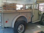
It's getting close. I have to say there's no feeling quite like putting the reflectors back on. You know you're almost to the end at that point.

Major to-do is still the wiring but we should knock that out in a couple of days next week. Keith_j is going dove hunting this weekend so I gave in and said he could take tomorrow off.

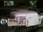
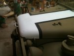
Today we finalized most of the painting to include the battle stripe on the hood. The wife was hesitant to do that but keeping with the authenticity of the 6 Day War we had to do it. I personally think it looks pretty cool. While most of the real vehicles look like someone painted them on free-hand with a brush (including the black border) I opted for masking tape and a couple of rattle cans of Rustoleum.

1) Battle stripe 1 in process
2) Battle stripe 2 after the black borders
3) Reflectors finally back on
 

Attachments

Keith_J

Well-known member
3,657
1,319
113
Location
Schertz TX
We are neck-deep into the wiring harness replacement with the color-coded Greek replacement. The rear is done and the front it in place, just not fully connected. The light switch is installed, I traced and numbered the colored wires for less confusion.

The original wiring harness was in sorry shape. Looks like three more days of sweating. But it will get done.
 

mkcoen

Well-known member
Steel Soldiers Supporter
5,637
381
83
Location
Spring Branch, TX
With Keith once again carrying the brunt of the load we finished most of the wiring yesterday. We're using a Greek, color-coded loom which has a couple of errors in it so with the schematic from that and also a copy of the original harness diagram we've been able to figure most of it out.

Right now we have headlights (high and low beam after the replacement of the dimmer switch), markers, tail lamps, dash lamps, and gauges working. Brake lights are currently dead and we haven't finished wiring the turn signals or horn. The horn button and mechanics are missing from the truck so a prior owner put a button on the dash and we're just going to wire to that.

The dimmer switch wasn't tried until after the wiring was hooked up and the inner fender panel buttoned down. I went to try switching the lights and discovered the switch was frozen. Took the panel back off, traded out switches, and BOOM we've got working high beams. Unfortunately one of the headlights is about 5 times brighter than the other on both high and low setting. They're both Wagner deuce headlights and appear to be brand new so not sure why the discrepancy.

The turn signals are going to be interesting. I've got newer 3 wire markers and tail lamps so will be wiring into those for the turn signals. The handle and flasher unit are already installed and part of the wiring from the original harness is still there. Hopefully that will go fairly smoothly.

Not sure what the issue with the brake lights are. I'm hoping it's not the switch as that's not the easiest item to access.
 

Barrman

Well-known member
5,253
1,760
113
Location
Giddings, Texas
Mark,
As I'm sure you two know. The brake like power comes from the 3 lever and then goes back. I have had several 3 levers that don't work on that circuit. Try connecting the leads at the brake switch before you condemn the switch.
 

mkcoen

Well-known member
Steel Soldiers Supporter
5,637
381
83
Location
Spring Branch, TX
Didn't spend a lot of time on it today but did verify we're getting power into the brake switch but still not functioning.

One of the issues is that the turn signals were an add-on by the military at some point (newer style connectors) but they run together with the brake lights and they're not completed yet so there could be an issue there.
 

Barrman

Well-known member
5,253
1,760
113
Location
Giddings, Texas
Solid state flasher box or the older style? If solid state, I will send you the best in my opinion wiring diagram for knowing which pin goes to what wire on systems with the solid state box and newer arm.
 

Keith_J

Well-known member
3,657
1,319
113
Location
Schertz TX
Whew! Had to re-read the post - noticed that you said 'sweating'; thought you said 'swearing'... :lol:

'Tanner'
Now it IS both, although a little cool front has dropped the temperature.

I want to trace the brake line pressure switch back to the light switch, then see if circuit 22 is energized.

IIRC, there were two added wires to the 3 lever switch which had the newer rubber plugs instead of Douglass connectors, these probably fed the turn signals into the 22A and B.
 

Keith_J

Well-known member
3,657
1,319
113
Location
Schertz TX
Got it. TM 9-2330-212-20 from the site's resources, Figure 2-61.

Looks like the light switch will have to be pulled and the two additional wires from the old wiring harness will have to be swapped into the new one. No biggie, these join the turn signal to the main.

I'm going to take a day to study this manual further.
 

Keith_J

Well-known member
3,657
1,319
113
Location
Schertz TX
Service Bulletin 9-203 may be an issue here. This is the installation of commercial turn signal kit. I need to read more to see if this is the case.
 

mkcoen

Well-known member
Steel Soldiers Supporter
5,637
381
83
Location
Spring Branch, TX
I printed off a copy of the TM 9-2320-212-20 section on turn signals. Haven't gone through it as I've been mowing my jungle this morning.
 

Keith_J

Well-known member
3,657
1,319
113
Location
Schertz TX
Enjoy the cooler weather, it brought down allergens so I'm a bit under the weather. Still getting up to speed on how this system works. How about we shoot for tomorrow?
 

mkcoen

Well-known member
Steel Soldiers Supporter
5,637
381
83
Location
Spring Branch, TX
More work on the wiring today. We found several spots in the Greek harness where the solder joints had come apart and other spots where the ends were not crimped properly. I'm hoping we don't have to go through the entire loom and check everything.

Was able to get a later model brake light switch from Advanced Auto Parts for $5.40 incl tax. NAPA wanted over $5 to ship one (plus the cost of the switch) from Phoenix and a M37 parts dealer (who shall remain nameless because I still buy other stuff there) wanted $90 for a NOS switch. Since this isn't a Concourse restoration the Advanced switch will be just fine.

We're going to wait to get the stop lights resolved before diving into the turn signals since they run through the same wires in the back half of the loom.
 

Keith_J

Well-known member
3,657
1,319
113
Location
Schertz TX
I used another MacGuyver wire to make BOTH stoplights work. Basically, this is a 3-bulb turn-brake/marker/BO marker tail lamp. The way it was wired was for right side BO stop, left side service stop. The way we wired it, both service markers run off the same lead but each brake had its own line, the left side brake didn't come on. So I made a wire to jumper the BO brake into the service brake at the trailer connection socket :doghead:

Now, this means the BO brake light will also illuminate the service brake lights, this is more of a safety feature than anything else since inadvertent use of the BO switch won't kill the service brake lights...hey, that is a SAFETY FEATURE.

Since the hydraulic brake line switch is inop., I used the bare switch leads as the switch while MKC observed. I love it when a plan comes together :beer:.

On the drive home, I had lots to think about with regards to the turn signals. It makes sense, sort of. Using the service brake lights as turn signals, BOTH must go through the flasher relay system so when braking and indicating a turn, the turn bulb flashes while the brake is steady on. Such is the logic in the flasher relay.

MKC discovered the end of the turn signal stalk is the pilot light, showing activation of the turn signals. It was covered with that nasty, stinky green paint. We got it cleaned off...one more step closer to perfection.
 

M-37Bruce

Active member
705
59
28
Location
Midlothian, VA
Questions

Any pic's of the broken wire/wires, any hint that it might have been broken from the outside? I have the same harness, thinking I might go a different route?
 
Top