• Steel Soldiers now has a few new forums, read more about it at: New Munitions Forums!

  • Microsoft MSN, Live, Hotmail, Outlook email users may not be receiving emails. We are working to resolve this issue. Please add support@steelsoldiers.com to your trusted contacts.

MEP-002A quit generating under full load. Where to start

Triple Jim

Well-known member
1,376
291
83
Location
North Carolina
I'll be interested in hearing how that test goes. My guess is that the regulator will try to make the generator put out 240v 3 phase power. Adjusting the output down to 208 may be possible if that happens.
 

rustystud

Well-known member
9,280
2,988
113
Location
Woodinville, Washington
Well I got my modified system up and running. I still need to adjust the regulator and figure out why my DC circuit breaker keeps kicking out. I jumped the breaker to get it started. I know that is a No ! No ! but I wanted to see if the regulator would regulate ! I'll get my notes and pictures posted soon. Just as soon as I get the system running correctly.
 

rustystud

Well-known member
9,280
2,988
113
Location
Woodinville, Washington
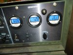
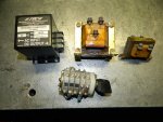
020.jpg021.jpg Got pictures of the running rig. I see I have to balance the load better . I'm still having trouble with the DC circuit breaker kicking off. Somewhere somehow I left off a wire that is really needed.
The second picture shows all the stuff I took out. I removed them and all the wires associated with them. Pretty much any wire that started with "X" was taken out.
We all need to get on "Jimc's" case and have him make up some more of these really great gauges ! I have 3 more generators to modify and I need some gauges !
 
Last edited:

rustystud

Well-known member
9,280
2,988
113
Location
Woodinville, Washington
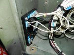
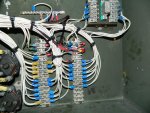
007.jpg012.jpg016.jpg

More pictures. In picture two you see the Diode pack (upper right hand corner) that "flashes" the generator. The only wire that had to be reinstalled was here. Wire number "P60A16" must be installed to "A1 7" on the module. Then the wire you designate as the positive field must be attached to "P60A16" .
By the way, does anyone know where "S7" is located ? It's somewhere on the engine. I'm not sure if this is suppose to be the starter solenoid or not. I have found many errors in the wiring compared to what is actually in the cabinets. It could just be that whoever serviced the units didn't really care to keep the wire numbers according to the manual.
 

Chainbreaker

Well-known member
1,797
1,992
113
Location
Oregon
Re: "S7" Not sure if your looking for physical location or schematic location...According to the control box schematic on my 1991 "S7" is identified as "Start Disc Sw". On schematic it is located right above the S1 Table (lower right corner of schematic diagram).

J16A <<------P59A16----"S7"----P55F16>> J16B

Furthermore, S7 is referenced on pg 4-38 of TM5-61115-584--12 under "DC Control System":

"The circuit between 25-27 of the master switch applies battery
voltage to the field flash resistor through diode (CR2).
This action applies field flashing current to the
exciter field. It sled applies power through diode
(CR1), which prevents starting set when the battery
polarity is reversed, and the closed contacts of the
start disconnect switch (S7) to the crank relay coil
(K3). When the crank, relay contacts close, a circuit
is completed to the starter solenoid (K6), which
closes and starts the cranking motor."

So...is "S7" the switch identified as "item 4" within the Starter Lockout Switch and Gear Assembly" on pg 4-32?
 
Last edited:

Ray70

Well-known member
2,597
5,921
113
Location
West greenwich/RI
Nice work Rusty, its looking good. If you decide to sell any of the stuff you removed, let me know. I wouldn't mind having a spare transducer on hand, if yours is still good.
 

Ray70

Well-known member
2,597
5,921
113
Location
West greenwich/RI
Yes, the frequency transducer. 2 out of my 4 machines have had transducers that died and I had to switch to digital gauges. I kind of like the original appearance of these machines so having a spare might not be a bad idea...
 

rustystud

Well-known member
9,280
2,988
113
Location
Woodinville, Washington
Well I found the problem to the breaker tripping. On A1 the number 1 wire nut is totally stripped out. It was just dangling there barely making contact. Problem is now I need a new A1 module as the temperature got so high it melted the stand-off studs holding the diodes. Hey Ray do you have a good A1 module to trade for an almost new Frequency transducer ?
 

rustystud

Well-known member
9,280
2,988
113
Location
Woodinville, Washington
It's fixed!!!!!! I will post a pic later. You can leave all old parts intact. It just requires two wires to the field terminals, and two wires to get L1 and L3 wherever. I landed mine on the reconnection switch. I mounted the new regulator in the ac output box. Literally 4 wires. No need for field flashing either.

Maybe someday I will rip more parts out, but as I see it, there is just no point. My hz and voltage gauges still work. My amp gauge never worked, so everything is the same. I don't plan to use three phase.

I am so happy!!

CrzyDave you never showed us your running generator ! I would like to see how you did yours.
 

rustystud

Well-known member
9,280
2,988
113
Location
Woodinville, Washington
Well I found the problem to the breaker tripping. On A1 the number 1 wire nut is totally stripped out. It was just dangling there barely making contact. Problem is now I need a new A1 module as the temperature got so high it melted the stand-off studs holding the diodes. Hey Ray do you have a good A1 module to trade for an almost new Frequency transducer ?
Well after installing a new A1 (starter relay , also called K1 ) I found I still had the circuit breaker kicking off. So after days of messing with this unit I finally found the culprit. I need a 55 OHM resistor inline with wire "P60A16" to my positive field wire. This way I keep the self exciting circuit. Without the resistor too much current was flowing and kicking off the breaker.
Now to button up everything and start on the next generator.
 

dangier

Member
Steel Soldiers Supporter
341
7
18
Location
Orange, VA
Good job on finding the problem! Does this mean a actual diagram of the process can be put up for anyone else wishing to take the leap? Maybe make it a sticky? Of course with the usual caveats on one taking the risk is on his/her own. :whistle:

I have three MEP's that I wish to keep stock, but have one 002 that I might entertain the option of gutting it.
 

rustystud

Well-known member
9,280
2,988
113
Location
Woodinville, Washington
Good job on finding the problem! Does this mean a actual diagram of the process can be put up for anyone else wishing to take the leap? Maybe make it a sticky? Of course with the usual caveats on one taking the risk is on his/her own. :whistle:

I have three MEP's that I wish to keep stock, but have one 002 that I might entertain the option of gutting it.
I suppose I could try and make a write up on what I did. It is a royal pain though since I don't have any fancy programs to help out with.
Oh by the way Ray. I came down with food poisoning last night and have been dealing with it even as I write this so I was not able to get to the post office today. Hopefully tomorrow I'll feel more human and can get down there and mail off the transducer.
 

CrzyDave

New member
32
0
0
Location
PA
I will get the pics and video up. It isn't necessary to gut anything like I said before. You can leave everything hooked up except a couple wires to the field excitation.
 

CrzyDave

New member
32
0
0
Location
PA


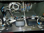
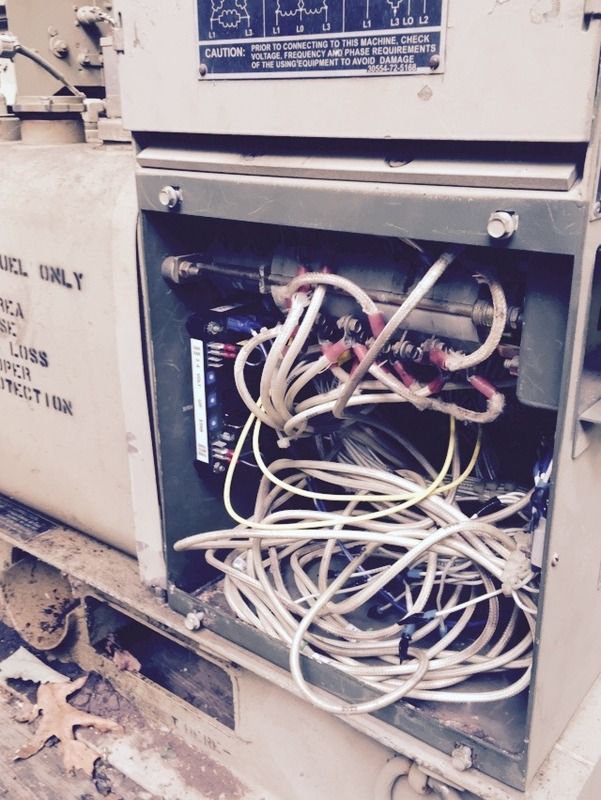
Here is where I mounted mine. Videos aren't working with photobucket. Anyone know a good host? If not, I'll take more still shots. This pic is about worthless for wiring details.
 
Last edited:
Top
AdBlock Detected

We get it, advertisements are annoying!

Sure, ad-blocking software does a great job at blocking ads, but it also blocks useful features of our website like our supporting vendors. Their ads help keep Steel Soldiers going. Please consider disabling your ad blockers for the site. Thanks!

I've Disabled AdBlock
No Thanks