• Steel Soldiers now has a few new forums, read more about it at: New Munitions Forums!

  • Microsoft MSN, Live, Hotmail, Outlook email users may not be receiving emails. We are working to resolve this issue. Please add support@steelsoldiers.com to your trusted contacts.

My M813 gets a turbo!

WillWagner

The Person You Were Warned About As A Child
Super Moderator
Steel Soldiers Supporter
8,539
2,758
113
Location
Monrovia, Ca.
That used to be done all the time, mostly on V8, V6 engines, long sweeps to the muffler. The flex will not make a sharp bend, but, there are short bellows type straight sections that can be installed at the inlet and outlet of the bend. I'll see if I can dig up a picture. When the engine torques from acceleration and or torque, it it wants to rotate opposite of engine rotation. Sitting in the seat, looking over the hood, the drivers side wants to lift. Under long hard engine braking events, well I guess it doesn't need to be a long event, the engine will twist in the direction of rotation.

Page 81. OAL is 7 inches, but I have cut it down to just past the bellows tigged it to piping and also welded marmon flanges to them so they are replaced easily. The longer, the better, shortening it gives you some deflection, but if left as close to the length it comes, it will last longer.

 
Last edited:

WillWagner

The Person You Were Warned About As A Child
Super Moderator
Steel Soldiers Supporter
8,539
2,758
113
Location
Monrovia, Ca.
Muffler is hard mounted to the engine, correct? If so, some type of flex should be about where the circle is IF the pipe is the one that exits the muffler.exhaust.jpg
 

US6x4

Well-known member
Steel Soldiers Supporter
1,233
2,242
113
Location
Wenatchee, WA
The muffler is hard mounted to the engine, but the chassis connection is not exactly a "hard mount" - it has some rubber isolators that provide a tiny bit of movement (more for vibrations though). That straight section is about 8" long so it's maybe barely long enough for that flex pipe.
20210807_174623.jpg
 

WillWagner

The Person You Were Warned About As A Child
Super Moderator
Steel Soldiers Supporter
8,539
2,758
113
Location
Monrovia, Ca.
Maybe, it will be OK. The stuff I did the shortening on were in Manitowoc cranes. The engine was isolated just like yours, and the exhaust was hard mounted to the chassis. The engine was allowed to vibrate and the shortened bellows was enough to let the engine do what it did. No torqueing like in an automotive application as you have. One of the others that comes to mind was a wheeled chassis that had a digger on the rear frame. Started with shortened stuff and ended up re designing the system. Let me see if I can find pics... Lots of off road stuff. It came back 2 or 3 times for exhaust leaks just because of the terrain and flex the vehicle had built into it. It was a n LA county flood control truck, made to dig out flood control channels. This was a +2010 retrofit, into a 1995 chssis so the exhaust needed to be leak free for the aftertreatment BS to work right. Ended up using the 7 inch bellows, leak free design and I never saw it return.....thank the lord! I did both the upper and drive engines in that!
 

WillWagner

The Person You Were Warned About As A Child
Super Moderator
Steel Soldiers Supporter
8,539
2,758
113
Location
Monrovia, Ca.
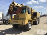
Found a pic. Not of the crap I did, but the exact vehicle. Gradall 4100. Took a 8.3 liter mechanical Cummins, C series, like in the 5T trucks, engine out of the drive chassis and installed a 9liter, full electronic, DOC, DPF, SCR in it and for the upper took a 5.9 mechanical 12 valve out and installed a 3.9, 4 cylinder tier 4i . Due to the amount of flex in the pig, heavy in the rear, lighter in the front with a compound low trans, the exhaust needed to have a mile of left right, up, down movement.No crappola, this thing articulated like a jeep. Was amazed. Reminded me of my deuce.
grade all.jpg
 

US6x4

Well-known member
Steel Soldiers Supporter
1,233
2,242
113
Location
Wenatchee, WA
I guess time will tell and this could be an experiment. If/when it cracks I'll see about getting a bellows section. I'll keep my fingers crossed.

That digger project sounds pretty involved. I'm surprised a construction rig would need aftertreatment but then again it is California...
 

US6x4

Well-known member
Steel Soldiers Supporter
1,233
2,242
113
Location
Wenatchee, WA
Not a big update tonight but I have finished a few more little things. I cut 8" off the bottom of the road draft tube because the first pressure pipe pushed it out over the frame and then I put a hose on it to route between the frame and block again. There was already a hole in the cab sheet metal to add a cushion P-clamp and another one will tie the hose to the bracket that's bolted to the side of the block.
20210808_172246.jpg

I've been designing all sorts of miscellaneous brackets for different parts while I wait for my paint guy to return to the paint shop.

There's a 3/16" L- bracket that ties the muffler mount to the block here:
20210810_201528.jpg

Here is the top most bracket to tie the reservoir tank to the firewall with a 10° slope built in and a tiny hole for the cap retention chain to attach to. Next to it is another 3/16" L-bracket to anchor the dipstick tube to the block.
20210810_202656.jpg

I had forgotten about the stack heat shield but after I found it again I remembered it needs new wider brackets also to fit around a 5" stack.
20210810_152124.jpg


I also painted the air horns and started making a new copper tube for them, but I'll post about that later. For now I have to wait for the radiator flex hose to plumb the reservoir tank to the oil cooler and keep working on the copper tube.
 

US6x4

Well-known member
Steel Soldiers Supporter
1,233
2,242
113
Location
Wenatchee, WA
I mounted up a few of the new brackets with my daughter's help so now the reservoir tank is on for good, the dipstick tube is anchored down and the muffler mount is tied to the block.

20210812_195959.jpg
20210812_200256.jpg
20210812_200015.jpg
20210812_200030.jpg


I also got the air horns bolted on for good with wires connected and I finished forming the copper tube. I'll post pics of the finished tube tonight since it was too dark for decent pics last night. For now, here's a before & after of the brass nuts being cleaned with aluminum brightener (It works really well).
20210812_200047.jpg
20210812_205454.jpg
 
Last edited:

US6x4

Well-known member
Steel Soldiers Supporter
1,233
2,242
113
Location
Wenatchee, WA
The copper air horn tube and the braided coolant hoses are now mounted up!

20210813_181713.jpg
20210814_071150.jpg
20210814_082141.jpg
20210814_082217.jpg

Meanwhile, I'm waiting on my last batch of parts to get baked in the oven and I'm waiting on the rubber hose to connect the turbo oil drain pipe to the block and the 45° elbow to connect the 1.25" reservoir coolant hose to the oil cooler.
20210813_130439.jpg
 

Mullaney

Well-known member
Steel Soldiers Supporter
Supporting Vendor
7,716
19,766
113
Location
Charlotte NC
The copper air horn tube and the braided coolant hoses are now mounted up!

View attachment 842433
View attachment 842434
View attachment 842435
View attachment 842436

Meanwhile, I'm waiting on my last batch of parts to get baked in the oven and I'm waiting on the rubber hose to connect the turbo oil drain pipe to the block and the 45° elbow to connect the 1.25" reservoir coolant hose to the oil cooler.
View attachment 842437
.
I have said it before US6x4 - but wow - that really looks nice.
Every new round of pictures make it all look just a little more impressive!

Is it a paint booth and drying room all in one?
Is that (grate) a waterfall system that helps capture and filter falling paint?
 

US6x4

Well-known member
Steel Soldiers Supporter
1,233
2,242
113
Location
Wenatchee, WA
.
I have said it before US6x4 - but wow - that really looks nice.
Every new round of pictures make it all look just a little more impressive!

Is it a paint booth and drying room all in one?
Is that (grate) a waterfall system that helps capture and filter falling paint?
Thanks Mullaney!

The shop is setup inline with a media blasting room, then a downdraft (air only) paint booth, then an oven and they are all able to drive through from one end to the other and they're big enough to fit an extended wheelbase 5 ton or a 10 ton inside.

It would be very cool to do a frame up on a rig with CARC powder coat.
 

US6x4

Well-known member
Steel Soldiers Supporter
1,233
2,242
113
Location
Wenatchee, WA
The reservoir tank is now fully plumbed and the coolant is back in the system with no leaks! I used a Continental (Goodyear) 52023 (23" long) flexible radiator hose to connect the 90° elbow off the tank to a new 45° elbow that i just finished. Since the cast hose barb on the oil cooler is 30° i went with a Stainless Bros 45° mandrel bent stainless elbow (601-03226-8150) to point the flex hose down into a curve to pass below the exhaust manifold with about 1" of clearance. The 45° elbow also points in towards the block a little. I have a black fire sleeve on the way to protect the hose from heat. So far it's turned out real nice 😁

20210812_200058.jpg
20210810_110459.jpg
20210810_110627.jpg
20210815_140842.jpg
20210815_140850.jpg
Since the vendor of the mandrel tubes with rolled beads was not around (Filler Neck Supply Company) I had the TIG guy add some raised bumps to help keep the clamps & hose in position.

20210815_141938.jpg


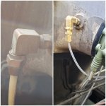
Today I also pulled the filter minder tube out of the firewall & intake manifold and replaced it with the tiny tube for the manifold pressure gauge and also secured the road draft tube extension & axle breather hose.
20210815_203359.jpg
20210814_195148.jpg
 
Last edited:
US6x4

Well-known member
Steel Soldiers Supporter
1,233
2,242
113
Location
Wenatchee, WA
The last batch of parts made it through the oven and the exhaust parts (excluding the heat shield) installed with no problems.
20210816_190857.jpg
20210816_195350.jpg
20210816_195410.jpg
Now that the pipe is located i will have to go back and adjust the muffler saddle mount to fit up tight to the muffler.
20210816_195414.jpg
20210816_195435.jpg
20210816_202057.jpg
The Torctite clamps on either side of the muffler torqued to 45 ft-lbs and the v-band clamp on the turbo discharge torqued to 32 in-lbs initially and then 45 in-lbs after tapping radially on the outside of the clamp with a small hammer.

20210816_202250.jpg
I love how menacing all these huge pipes look seeing them crammed in the engine bay with the side panel down. Hehehe...
 

US6x4

Well-known member
Steel Soldiers Supporter
1,233
2,242
113
Location
Wenatchee, WA
Tonight all I did was adjust the muffler saddle bracket to mate up with the muffler and get all of that cinched down so no new pics tonight.

I did want to expand on my flavor of turbo and how I ended up there. What I was shooting for was a divided entry turbo for the improved air velocity/ quicker spooling because of that hole between 3rd & 4th. Since I have Jacobs 25B jake brakes installed I was searching for the auto-lash adjusters that enable the jakes to work with a divided entry turbo. In my research I came across the BHT3B turbos that had a Map Width Enhancement slot milled into the compressor inlet which was said to eliminate the pressure surging that was causing issues with jake brakes that did not have auto-lash adjusters (among other things). Jim Blaylock mentioned to me that they had fixed the jake brake problem by making mods to the turbo so that slot must be what he was referring to.
https://www.steelsoldiers.com/threads/jake-brake-25a-vs-25b-their-use-with-a-pulse-manifold.185202/

I finally tracked down the auto-lash adjusters but since they were $600+ and since the BHT3B was about $200 over the HT3B I decided to get a BHT3B and I could always get the auto-lash parts later if this didn't work out.

I talked to a BorgWarner distributor in my neck of the woods to order a BHT3B but have it put together with a divided entry 26cm turbine housing instead of the typical 32cm housing to decrease the spooling time.
I had only found 1 picture of a divided entry 26cm turbine housing so I figured it must be a thing and the distributor didn't say that it didn't exist. What I ended up with was a 26cm single entry turbo which turned out to be a new off-the-shelf Schwitzer 167050 BHT3B. So I didn't get the divided entry I thought I was getting, but on the upside I didn't have to pay the $300 custom assembly fee and I know for sure that I won't have issues with my jakes. I decided to keep it and not hassle with return shipping and all that mess. I'm assuming now that divided entry 26cm turbine housings aren't a thing (at least not any more).
20210817_194247.jpg
 
Last edited:

US6x4

Well-known member
Steel Soldiers Supporter
1,233
2,242
113
Location
Wenatchee, WA
I'm still waiting for the little 7/8" x 3" long hose to connect the turbo oil drain to the block fitting and that is all that's holding me up from starting my engine. It never arrived last night so I have to wait till next week 😩

While I wait I've swapped the paint pattern on the air canister and the heater canisters so that when they get mounted back on they will match the trucks paint pattern (they're switching sides of the truck). I've also relocated the filter minder tube and I've started to mock up the piping between the air filter and the turbo. It looks like I can trim 4" off the straight section of the factory intake tube and roll a new bead on the end to make it work. My 6" splice section (in bubble wrap) is too long and will need to be trimmed down to 4".

20210821_140539.jpg
20210821_140513.jpg
20210821_143110.jpg
20210821_143121.jpg
 

hethead

Active member
147
216
43
Location
Seattle, WA.
I'm still waiting for the little 7/8" x 3" long hose to connect the turbo oil drain to the block fitting and that is all that's holding me up from starting my engine. It never arrived last night so I have to wait till next week 😩

While I wait I've swapped the paint pattern on the air canister and the heater canisters so that when they get mounted back on they will match the trucks paint pattern (they're switching sides of the truck). I've also relocated the filter minder tube and I've started to mock up the piping between the air filter and the turbo. It looks like I can trim 4" off the straight section of the factory intake tube and roll a new bead on the end to make it work. My 6" splice section (in bubble wrap) is too long and will need to be trimmed down to 4".

View attachment 843049
View attachment 843050
View attachment 843051
View attachment 843052
I for one am looking forward to hearing all about how she runs. Nice work!
 

US6x4

Well-known member
Steel Soldiers Supporter
1,233
2,242
113
Location
Wenatchee, WA
The heater is now mounted in its new location on the driver's side fender and my last two parts I needed arrived today so this turbo is ready to start whistling!

20210822_111639.jpg
20210823_171758.jpg

The flame guard is made by Holly (p/n HL571232ERL) and is smooth but grippy on the outside like shark skin and the inside is woven fibers just like a welding blanket. Wrapped around this hose it does double duty shielding the hose from both heat and abrasion.
20210823_171904.jpg
20210823_171911.jpg
20210823_172216.jpg

The 7/8" ID x 3" long hose went on firm as it stretched over the 1" OD hydraulic tube and then it slipped on real nice over the 7/8" OD brass fitting. This bright orange-red hose looks a bit out of place on this engine but it's kinda fun at the same time.
20210823_174003.jpg
20210823_193209.jpg
20210823_193234.jpg
The socket head cap screws got torqued to 18 ft-lbs. I'm pretty excited to get this part on as it was the last piece needed to run. I ran out of time after I got the drain tube installed so hopefully tomorrow I'll add some oil to the turbo with a turkey baster, put the oil feed line back on and see if my dying batteries can turn this engine on!
 

US6x4

Well-known member
Steel Soldiers Supporter
1,233
2,242
113
Location
Wenatchee, WA
It's alive!!!


The low batteries took some coaxing but eventually they spun it over enough to fire. Revved it up to 1200 rpm a few times to hear the whistle, let it warm up to 130°F and then shut it down.

I still have to finish the piping from air cleaner to turbo, install the stack, and cut a hole in the engine compartment side panel.

No leaks, no fires, no rattles, and no boost registering on the manifold pressure gauge...

I'm guessing boost doesn't really build until it's under a load.
 
Top
AdBlock Detected

We get it, advertisements are annoying!

Sure, ad-blocking software does a great job at blocking ads, but it also blocks useful features of our website like our supporting vendors. Their ads help keep Steel Soldiers going. Please consider disabling your ad blockers for the site. Thanks!

I've Disabled AdBlock
No Thanks