• Steel Soldiers now has a few new forums, read more about it at: New Munitions Forums!

  • Microsoft MSN, Live, Hotmail, Outlook email users may not be receiving emails. We are working to resolve this issue. Please add support@steelsoldiers.com to your trusted contacts.

MEP 802A M8 Percent Load Gauge Issue

CallMeColt

Well-known member
Supporting Vendor
1,010
1,465
113
Location
Wilson County, Texas
Everyone,

I normally keep my troubleshooting issues on one thread for one machine, but I searched a bunch, tried a bunch on my own, and have hit a dead end.

https://www.steelsoldiers.com/threads/mep-802a-fix-up-thread-3-0.212213/

The search function doesn't work well, so forgive me if it is on here somewhere, but I didn't find it.

But if it's not, I figured a specific thread for this may be a good one to have on it's own in case others have the same problem.

I have a unit where the M8 Percent Load gauge reads, but exactly half what it should. It is making me this it's just not picking up a leg like its supposed too.

So far here is what I have done;

-Replaced M8 with a known good.
-Traced wires for anything broken/loose. All seem okay.
-Check S6 to be sure there was a connection between 26 & 28 as there should be when in 240v single phase mode. There is.
-Rotated S6 until my hand was tired and sprayed it with contact cleaner.

Hoping that someone has a quick "You forgot to check this" or something that I have glazed over!

Thanks
 

Guyfang

Moderator
Staff member
Moderator
16,667
23,828
113
Location
Burgkunstadt, Germany
Kurt has it right. This happens VERY often. I first ran in to this with a ROPU water purification unit. The gen set was a 30 KW. The CT wires were wrapped like a 60KW. Every time the big electric motor started, drawing about 26 KW startup, the gen set sounded like it would jump off the trailer, and shut down.
 

CallMeColt

Well-known member
Supporting Vendor
1,010
1,465
113
Location
Wilson County, Texas
The correct number of turns of each wire thru the CT? For the 802 it's 8 turns. For the 803 it's 4 turns.
I have not opened up the back yet to look but that makes perfect sense. I'll need to pull the top off and look back there to see if it's the issue. It didn't look at first glance that it was pulled off but that doesn't mean it wasn't.
 

Farmitall

Well-known member
Steel Soldiers Supporter
544
276
63
Location
Eubank, KY
I have not opened up the back yet to look but that makes perfect sense. I'll need to pull the top off and look back there to see if it's the issue. It didn't look at first glance that it was pulled off but that doesn't mean it wasn't.
Directly underneath that current transformer is a favorite place for mice to build a large nest. Along with that comes their urine and turds. When you pull off the cover, check the cleanliness and tightness of all the connections on the terminal strip below the current transformer.
 

CallMeColt

Well-known member
Supporting Vendor
1,010
1,465
113
Location
Wilson County, Texas
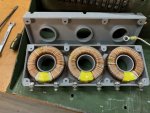
So, I opened up the top to take a look. I was incorrect about it not being removed before, got it mixed it up with the other one I had worked on (to many different projects going on at once). With that said, there is nothing obvious to me that was changed or messed with on this side. Just dusty & the typical spots where some wires have started to rub more than they should have on the enclosure but have not rubbed through.

I checked S8 between 42 & 44. It is good. I have connection all the way from 44 on S8 to 26 on S6 and everything in between.

On the CT, I didn't check every wire, but picked a random wire number on each loop & found it MORE than 4 times. The zip ties seemed to be original ones and nothing disturbed as I said before, but, that doesn't mean it wasn't. I should have traced the proper wires that would give me the percent load reading but was just doing something quick before it got to late & dark.

Nothing else seemed loose, broken, or missing.

Maybe just bop everything a bit with a rubber mallet since it probably sat a while? I dunno. Or, the CT is bad, but, I'd think other readings would be catty-wompus if that was the case. Going through and 100% confirming the wires on the CT needs to be done.

I got in in my garage now.

318076274_974115650644596_1039913985279109724_n.jpg 317954181_1338691030282308_393331269991203686_n.jpg 318017340_829762574951125_1621939009480064337_n.jpg
 

Farmitall

Well-known member
Steel Soldiers Supporter
544
276
63
Location
Eubank, KY
So, I opened up the top to take a look. I was incorrect about it not being removed before, got it mixed it up with the other one I had worked on (to many different projects going on at once). With that said, there is nothing obvious to me that was changed or messed with on this side. Just dusty & the typical spots where some wires have started to rub more than they should have on the enclosure but have not rubbed through.

I checked S8 between 42 & 44. It is good. I have connection all the way from 44 on S8 to 26 on S6 and everything in between.

On the CT, I didn't check every wire, but picked a random wire number on each loop & found it MORE than 4 times. The zip ties seemed to be original ones and nothing disturbed as I said before, but, that doesn't mean it wasn't. I should have traced the proper wires that would give me the percent load reading but was just doing something quick before it got to late & dark.

Nothing else seemed loose, broken, or missing.

Maybe just bop everything a bit with a rubber mallet since it probably sat a while? I dunno. Or, the CT is bad, but, I'd think other readings would be catty-wompus if that was the case. Going through and 100% confirming the wires on the CT needs to be done.

I got in in my garage now.

View attachment 885611 View attachment 885610 View attachment 885609
Bopping anything with a rubber mallet isn't going to resolve the problem. Lots of those connections on the terminal strips look dirty/somewhat corroded.

I'd follow the schematic, verify the wire number on each winding of the current transformer and make sure they go to their appropriate connection and remove and clean the connections for each one.

That current transformer is an inductive pickup to send a voltage signal to the load meter.

Randomly checking things is not a good practice for troubleshooting, that's just shooting in the dark and hoping to get lucky. You need to go through it methodically, making notes of your connections and readings and not skip through the procedure willy nilly.

There is a corroded or misconnected wire in the circuit somewhere......a mallet isn't going to find it, visual inspection, cleaning and A METER will.
 
Last edited:

CallMeColt

Well-known member
Supporting Vendor
1,010
1,465
113
Location
Wilson County, Texas
Bopping anything with a rubber mallet isn't going to resolve the problem. Lots of those connections on the terminal strips look dirty/somewhat corroded.

I'd follow the schematic, verify the wire number on each winding of the current transformer and make sure they go to their appropriate connection and remove and clean the connections for each one.

That current transformer is an inductive pickup to send a voltage signal to the load meter.

Randomly checking things is not a good practice for troubleshooting, that's just shooting in the dark and hoping to get lucky. You need to go through it methodically, making notes of your connections and readings and not skip through the procedure willy nilly.

There is a corroded or misconnected wire in the circuit somewhere......a mallet isn't going to find it, visual inspection, cleaning and A METER will.
You'd be supersized how many times a rubber mallet has loosened things up that were stuck on equipment that has sat, but I get your point.

I don't quite understand how the CT works, and am not sure if it has anything that moves on the inside... that is why I thought of it. Had contactors not want to close in the past that took hitting once or twice to close their first time and then worked fine after that.

The reason I "randomly" picked wires was to avoid spending hours and hours checking to see if there were 4 vs 8 loops as suggested above on each wire. If everything hasn't been disturbed since manufacturing, it probably wasn't re-looped improperly. That is why I said a random wire in each loop was checked to see if it was there more than 4 times. Checking ahead for a few obvious things quickly can save a lot of time. I'm probably one of the more thorough & longest note taking troubleshooters here on this forum. But, I am also ignorant on a lot of things so in the name of saving myself a lot of time, I will ask for help.

As I said, I have a connection through the entire circuit as I should for the M8. This is confirmed with a meter. That is why I said a 100% check of the wires through the CT is the next step, but wanted to share my progress in case anyone else had another hint that would save me the hours of work that might not need to be done removing all the wires and sending them back through on the CT. If everything is going through the CT as it should, and the circuit is as it should be for M8, I am thinking something is wrong with the CT or one of the little wires coming off it is connected incorrectly. But, no other readings are off so it is odd. My guess is there is a testing procedure for it in the TM and I will try and dig it up. I also will print the diagram and 1 by 1 confirm nothing with going to the wrong connection on any of the TB's.

Now that it's inside, night work can happen. :)
 

CallMeColt

Well-known member
Supporting Vendor
1,010
1,465
113
Location
Wilson County, Texas
Man, it's so much more pleasurable to trouble-shoot these machines inside of a heated shop that's well-lit with a cup of coffee and a little music. With your determination, you'll find the problem.
In all fairness, it was only right outside of my garage, haha. I just had other projects inside. But, not that the top is off I had to make room as I didn't want it getting rain and stuff in there. It's dusty but doesn't look like it really got wet in there so far.

But yeah, inside work is great. I have full HVAC, computer, smart TV, internet, and everything in my shop. I really wish I could fit my LMTV in there.
 

Farmitall

Well-known member
Steel Soldiers Supporter
544
276
63
Location
Eubank, KY
You'd be supersized how many times a rubber mallet has loosened things up that were stuck on equipment that has sat, but I get your point.

I don't quite understand how the CT works, and am not sure if it has anything that moves on the inside... that is why I thought of it. Had contactors not want to close in the past that took hitting once or twice to close their first time and then worked fine after that.

The reason I "randomly" picked wires was to avoid spending hours and hours checking to see if there were 4 vs 8 loops as suggested above on each wire. If everything hasn't been disturbed since manufacturing, it probably wasn't re-looped improperly. That is why I said a random wire in each loop was checked to see if it was there more than 4 times. Checking ahead for a few obvious things quickly can save a lot of time. I'm probably one of the more thorough & longest note taking troubleshooters here on this forum. But, I am also ignorant on a lot of things so in the name of saving myself a lot of time, I will ask for help.

As I said, I have a connection through the entire circuit as I should for the M8. This is confirmed with a meter. That is why I said a 100% check of the wires through the CT is the next step, but wanted to share my progress in case anyone else had another hint that would save me the hours of work that might not need to be done removing all the wires and sending them back through on the CT. If everything is going through the CT as it should, and the circuit is as it should be for M8, I am thinking something is wrong with the CT or one of the little wires coming off it is connected incorrectly. But, no other readings are off so it is odd. My guess is there is a testing procedure for it in the TM and I will try and dig it up. I also will print the diagram and 1 by 1 confirm nothing with going to the wrong connection on any of the TB's.

Now that it's inside, night work can happen. :)

1670363947723.png
This picture is a basic explanation

This is what a "current transformer" looks like schematically.

The windings through the hole in the current transformer would represent the "Primary" winding in the picture and the secondary windings would be the studs at each set of loops.

1670364618136.png

The reason there is 3 of them is for monitoring current on each of the 3 phases of the generator windings.

No moving parts. They work inductively.

There should be continuity between each set of studs. That would show that the secondary windings within are intact.
 
Last edited:

Farmitall

Well-known member
Steel Soldiers Supporter
544
276
63
Location
Eubank, KY
Actually they are not potted on the inside. Someone posted a pic a few years ago of a CT opened up. Just 3 separate coils suspended by the plastic housing.

** Warning
If the output of the CT doesn't have a load on it, it can generate extremely high, lethal voltage
Thanks for the clarification on the potting and the high voltages. I had/have not opened one up to check the actual construction, it was just a guess on my part, having seen other types having been potted. I edited my post to "possibly" potted but even that doesn't apply here.(y)

One would think that the military would have specified potted cores but by not being potted, they might be rebuildable at some level or it was just a cost reducing/weight reduction factor in production.
 

CallMeColt

Well-known member
Supporting Vendor
1,010
1,465
113
Location
Wilson County, Texas
Thank you for the explanation. From what you said, what I know, and what the wire diagram shows, it makes very clear sense to me now on exactly what it is doing, and how it is doing it.

Side note... just by luck, I found a complete paper set of TM's on top of the dumpster today that came in handy. A .PDF is great, but a book in hand has it place as well.

318218703_561906225770286_2996081145919952417_n.jpg

CT tested correctly as per the TM.

So, I put in 3 hours after work. I traced ALL the wires off the CT and beyond. Even made sure all the connections inside the switches were making the connections they should. By all means, these wires and connections make quite the back and forth!

J6 was clean.

All I did swap around some wires to match the diagram exactly but I don't think it mattered. For example, On S6, it has a newer style and it had the connection from M8 run to 26 instead of 28. There were some wire like this on the CT as well. Ultimately, it made no difference.

I really was scratching my head since there were not bad or missing connections and the CT tested correctly.

I took the CT3 wires off and tested... got proper reading on M8 with a full 240v load. My guess is that CT3 was not working correctly for some reason. I hooked them back up, and while running, hit the CT with a rubber mallet. Reading jumped up to where it should be.

I had assumed like Farmitall that the inside was all rubber to suspend whatever was inside. But, after reading what kloppk said, I bed the inside is rusted/corroded or something. It probably won't last, but at least I found the problem and know where it is. I have a CT I left in an extra wire harness that I was going to sell. May pull it and test it to see if it is okay. If it looks better, I may swap it. That unit sat outside with no top for a while though.

I really appreciate all the input and I hope this helps others if they find themselves with the same issue. I will come back later and modify the post with a bit more detail so anyone trying to use this to troubleshoot can use it as a guide.
 

loosegravel

Just a retired mechanic who's having fun!
504
890
93
Location
Enumclaw, Washington
Thank you for the explanation. From what you said, what I know, and what the wire diagram shows, it makes very clear sense to me now on exactly what it is doing, and how it is doing it.

Side note... just by luck, I found a complete paper set of TM's on top of the dumpster today that came in handy. A .PDF is great, but a book in hand has it place as well.

View attachment 885718

CT tested correctly as per the TM.

So, I put in 3 hours after work. I traced ALL the wires off the CT and beyond. Even made sure all the connections inside the switches were making the connections they should. By all means, these wires and connections make quite the back and forth!

J6 was clean.

All I did swap around some wires to match the diagram exactly but I don't think it mattered. For example, On S6, it has a newer style and it had the connection from M8 run to 26 instead of 28. There were some wire like this on the CT as well. Ultimately, it made no difference.

I really was scratching my head since there were not bad or missing connections and the CT tested correctly.

I took the CT3 wires off and tested... got proper reading on M8 with a full 240v load. My guess is that CT3 was not working correctly for some reason. I hooked them back up, and while running, hit the CT with a rubber mallet. Reading jumped up to where it should be.

I had assumed like Farmitall that the inside was all rubber to suspend whatever was inside. But, after reading what kloppk said, I bed the inside is rusted/corroded or something. It probably won't last, but at least I found the problem and know where it is. I have a CT I left in an extra wire harness that I was going to sell. May pull it and test it to see if it is okay. If it looks better, I may swap it. That unit sat outside with no top for a while though.

I really appreciate all the input and I hope this helps others if they find themselves with the same issue. I will come back later and modify the post with a bit more detail so anyone trying to use this to troubleshoot can use it as a guide.
This is a very detailed explanation of what you found. It’s what helps to make this an awesome forum. Great job!
 

Guyfang

Moderator
Staff member
Moderator
16,667
23,828
113
Location
Burgkunstadt, Germany
Thanks for the clarification on the potting and the high voltages. I had/have not opened one up to check the actual construction, it was just a guess on my part, having seen other types having been potted. I edited my post to "possibly" potted but even that doesn't apply here.(y)

One would think that the military would have specified potted cores but by not being potted, they might be rebuildable at some level (Pluck and Chuck. No repair. Trash can) or it was just a cost reducing/weight reduction factor in production.
Open to read comment
 

CallMeColt

Well-known member
Supporting Vendor
1,010
1,465
113
Location
Wilson County, Texas
Open to read comment
Guyfang, you are the most experienced I know on here with the generators... have you experience when I have above? Do you think my symptom was internal and my hitting it is what got it going, or by chance that just jolted something somewhere else? I really traced EVERY wire in a diagram & the meter showed it good. Just wondering if you had something like this pop up where a CT tested good but still wasn't giving a reading as it should have. Or maybe something else was interfering with the wire in the loops from being sensed? I'm really baffled by it. Appreciate your input as always.
 
Top
AdBlock Detected

We get it, advertisements are annoying!

Sure, ad-blocking software does a great job at blocking ads, but it also blocks useful features of our website like our supporting vendors. Their ads help keep Steel Soldiers going. Please consider disabling your ad blockers for the site. Thanks!

I've Disabled AdBlock
No Thanks