• Steel Soldiers now has a few new forums, read more about it at: New Munitions Forums!

  • Microsoft MSN, Live, Hotmail, Outlook email users may not be receiving emails. We are working to resolve this issue. Please add support@steelsoldiers.com to your trusted contacts.

Looking for M1078A1 ABS troubleshooting guide

aw113sgte

Well-known member
Steel Soldiers Supporter
637
970
93
Location
La Crosse, WI
@hike
Once you have the TMs
I did see a “troubleshooting data bus” procedure in the TM and it will step you through the process taking readings from your truck, using the ICE box that came with your kit.
If only someone would help with the software for msd/ice...so far I've had no luck finding it. I do have the IETMs though but that doesn't allow use of the various testing hardware
 

Lostchain

Well-known member
Steel Soldiers Supporter
285
588
93
Location
Portland, OR
Did you get a DS package with the IETM ? if you installed it it would have a DS Test Set Selector application that lets you pick "Serial ICE" which is what you have
 

aw113sgte

Well-known member
Steel Soldiers Supporter
637
970
93
Location
La Crosse, WI
Did you get a DS package with the IETM ? if you installed it it would have a DS Test Set Selector application that lets you pick "Serial ICE" which is what you have
I got 2 DVDs with mine, first had ems2, and multiple IETMs, the second disc had more IETMs, but no ICE or ds test set selector that I saw.
 

hike

—realizing each day
Steel Soldiers Supporter
532
840
93
Location
Texas Hill Country
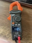
New resistor arrived and tested, isolated, I wanted to check before removing the PDP again.

IMG_3669.jpeg

It looks like we have a winner. I hopefully that is our only ABS issue—
 

hike

—realizing each day
Steel Soldiers Supporter
532
840
93
Location
Texas Hill Country
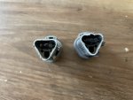
Well, of course it was not just R13 under the PDP; R12 near the Cat ECU is also looking like blackened redfish, in and out.

IMG_3673.jpeg

So, the question is since everything works, EXCEPT ABS do/did we have:
1— old resistors that died;
2— a bad ABS ECU;
3— a bare hot wire grounding out?

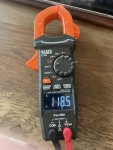
I am not confidant in my continuity testing, and I haven't tested anything at the ABS ECU; still we dropped new 120 ohm resistors in at R12 (I assume R12 is also a 120 ohm resistor?) and R13.

IMG_3669.jpeg

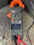
ABS light is OFF at the dash, I do not feel heat at either resistor, BUT the voltages at the Deutsch testing connection do not add up to less than 5.0v.

'D' should always be less than 2.5v, right?
IMG_3686.jpeg

'C'
IMG_3685.jpeg

We have 60 ohms between 'C' and 'D'.

IMG_3690.jpeg

What thoughts do we have? Over voltage by 15 hundreds, though everything appears to work. Headed out to plug in the DPA III+ to see if the J1939 side works now—
 

aw113sgte

Well-known member
Steel Soldiers Supporter
637
970
93
Location
La Crosse, WI
Well, of course it was not just R13 under the PDP; R12 near the Cat ECU is also looking like blackened redfish, in and out.

View attachment 910640

So, the question is since everything works, EXCEPT ABS do/did we have:
1— old resistors that died;
2— a bad ABS ECU;
3— a bare hot wire grounding out?

I am not confidant in my continuity testing, and I haven't tested anything at the ABS ECU; still we dropped new 120 ohm resistors in at R12 (I assume R12 is also a 120 ohm resistor?) and R13.

View attachment 910655

ABS light is OFF at the dash, I do not feel heat at either resistor, BUT the voltages at the Deutsch testing connection do not add up to less than 5.0v.

'D' should always be less than 2.5v, right?
View attachment 910652

'C'
View attachment 910653

We have 60 ohms between 'C' and 'D'.

View attachment 910654

What thoughts do we have? Over voltage by 15 hundreds, though everything appears to work. Headed out to plug in the DPA III+ to see if the J1939 side works now—
So ABS has to turn off that light, at least on my A1R. If the ABS computer is disconnected or not functioning that light will still be on.
 

GeneralDisorder

Well-known member
Steel Soldiers Supporter
2,051
5,257
113
Location
Portland, OR
My guess is someone hooked up incorrectly or applied power to the coms port and blew those resistors.

Your DC meter readings on the coms bus is showing the meters averaged interpretation of the 5v square wave. It's not going to be exactly 2.5v because the on and off times are not exactly 50/50. You really need a scope to know for sure what's on the bus but I wouldn't worry about that. Try connecting now that the resistors are in place.

If you AC couple the meter it might read more accurately. Regardless - if it works don't worry about it. The signal is digital.
 
Last edited:

hike

—realizing each day
Steel Soldiers Supporter
532
840
93
Location
Texas Hill Country
So ABS has to turn off that light, at least on my A1R. If the ABS computer is disconnected or not functioning that light will still be on.
Maybe. The light was off until we replaced the ABS light circuit breaker which had been removed. Since installing a new circuit breaker light has been on. The DPA III+ has been finding faults with voltage or open circuit on ABS while all other ECU's reported. Replacing R12 and R13 (both burned up) has:

1— turned the dash ABS light OFF;
2— returned resistance between 'C' and 'D' at Deutsch plug to 60 ohms;
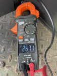
3— changed the voltage at 'C' to 2.671v and 'D' to 2.571v, ('D' should be below 2.5v);
4— opened J1939 comms;
5— stopped ABS faults.

We plugged in our DPA III+ and now both J1939 and J1708/1587 connect, No faults reported.

Hopefully all we had was two burned up resistors, though why?
I think I'll button her up in the morning and take her out for a drive, hoping the 15 hundredths of a volt over isn't going to burn something up—
 
Last edited:

aw113sgte

Well-known member
Steel Soldiers Supporter
637
970
93
Location
La Crosse, WI
Maybe. The light was off until we replaced the ABS light circuit breaker which had been removed. Since installing a new circuit breaker light has been on. The DPA III+ has been finding faults with voltage or open circuit on ABS while all other ECU's reported. Replacing R12 and R13 (both burned up) has:

1— turned the dash ABS light OFF;
2— returned resistance between 'C' and 'D' at Deutsch plug to 60 ohms;
3— changed the voltage at 'C' to 2.671v and 'D' to 2.571v, ('D' should be below 2.5v);
4— opened J1939;
5— stopped ABS faults.

We plugged in our DPA III+ and now both J1939 and J1708/1587 connect, No faults reported.

Hopefully all we had was two burned up resistors, though why?
I think I'll button her up in the morning and take her out for a drive, hoping the 15 hundredths of a volt over isn't going to burn something up—
Right, the circuit breaker is required. Mine was the same (missing circuit breaker, no light). If everything else is correct except the abs computer the light will be on.
 

hike

—realizing each day
Steel Soldiers Supporter
532
840
93
Location
Texas Hill Country
Thank you all. Good comments and solid advice as usual. We'll button up in the morning and drive to lunch with friends. Maybe even try to test the ABS system on the way.

What a great forum, I am grateful for you all. It would have taken much longer with less confidence without your cajoling and suggestions. I hope one day I may contribute, as well—
 

GeneralDisorder

Well-known member
Steel Soldiers Supporter
2,051
5,257
113
Location
Portland, OR
Thank you all. Good comments and solid advice as usual. We'll button up in the morning and drive to lunch with friends. Maybe even try to test the ABS system on the way.
If you can get the ABS to activate on anything less than ice or snow my hat's off to you sir.
 

GeneralDisorder

Well-known member
Steel Soldiers Supporter
2,051
5,257
113
Location
Portland, OR
Thank you. I do have mud now. I'll try that and report back so we'll know if we should add to the list—
Maybe! These things have SUPERB traction due to literally tons of weight on a massive contact patch so it's pretty hard to lock up the tires.

Put the tires at 90 psi for the attempt.
 

aw113sgte

Well-known member
Steel Soldiers Supporter
637
970
93
Location
La Crosse, WI
Maybe! These things have SUPERB traction due to literally tons of weight on a massive contact patch so it's pretty hard to lock up the tires.

Put the tires at 90 psi for the attempt.
I guess that's an "advantage" of my MTV with no box....I regularly lock up tires going out of my steep driveway on tarmac. Good for abs testing....
 

hike

—realizing each day
Steel Soldiers Supporter
532
840
93
Location
Texas Hill Country
Now for the rest of the story:

After using our plaza Arduino CTIS ECU for a while we decided to swap in our Dana Spicer M939A2 CTIS ECU and reprogram it. The plaza unit is great and works fine we just want both units setup the same so to have a backup, and the Dana Spicer unit being push button is easier to operate while driving and offers less glare at night.

Upon installing the Dana ECU the ABS fault is back. Hooking up the diagnostics finds everything working, we can program the Dana unit, just the ABS fault is back. While testing the settings in the reprogrammed M939A2 ECU we smell that sweet burnt plastic smell. R12 and R13 are both fried.

After checking the schematics for the M1078A1 P110 plug at the CTIS ECU and comparing to the schematics for the M939A2 CTIS ECU it appears the M1078A1 and M939A2 wiring harnesses routed a few items differently at what appears to be the (M1078A1's P110) connector to the CTIS ECU.

Since @GeneralDisorder has suggested the Dana Spicer ECU's do not connect across J1939 and we can connect to our Dana Spicer using J1708; I am thinking IF using the M939A2 CTIS ECU in our M1078A1 we need to disconnect 'G'.

note: The plaza Arduino CTIS ECU does not connect to the J1939 circuit at all, ('G', 'W', 'X').

M939A2 DIFFERENCES
1— no diagnostic connections listed;
2— speed signals routed through 'Y' and 'K';
3— pressure switch 'B' also used, routed through 'L';
4— additional ground routed through 'V';
5— 'a', 'N', 'U', 'M' and 'A' not used.

CONFLICTS
The M939A2 CTIS ECU uses — M1078A1 uses:

'G' for the Control Switch 'A' — the M1078A1 routes control switch 'A' to ground through 'F' and uses 'G' for J1939 (+);
note: if you follow the M1078A1 J1939 (+) wire it does connect to R13 and R12.

'M' for the Wrecker Only Ground — the M1078A1 routes ground through 'F' and uses 'M' for optional power;

Should be OKAY?
The M939A2 CTIS ECU uses — M1078A1 uses:

'W' for the Control Switch 'B' — the M1078A1 routes control switch 'B' to ground through 'F' and uses 'W' for J1939 (shield);

'b' for the Pressure Transducer 'A' — the M1078A1 routes pressure transducer 'A' to common through 'j' and uses 'b' for power;
'j' for the Pressure Transducer 'B' — the M1078A1 routes pressure transducer 'B' to power through 'b' and uses 'j' for common;

M939A2 schematic
View attachment 913437

M1078A1 <18500 schematic
View attachment 913438


As I fried the last of my 120ohm resistors I'll have to await the arrival replacements, next up: to see if disconnecting 'G' may allow using the M939A2 CTIS ECU in our M1078A1 unit without conflicting with the J1939 system and causing a fault in the ABS system.

Thinking about how everything lines up and wishing to minimize changes to the M1078A1's wiring harness I decided to pull the 'G', 'W', and 'X' pins from the M939A2 CTIS ECU connector. Once I had pulled all three (matching the plaza Arduino CTIS, too) the ABS fault code dropped, and our diagnostics on both J1939 (not for CTIS) and J1708 all work. Once we receive new resistors we'll recheck the system voltages and ohms.

Being a rainy day here I took her out on a country road and tested the ABS system. Not sure I felt pluses in the pedal, though hammering the brakes at speed with nothing in the back didn't put us in a skid on a slick road. They are likely working or not yet needed.

Hopefully, isolating the M939 CTIS ECU from the J1939 system will be a longer term fix and keep the M939A2 CTIS ECU system conflict free on our M1078A1—
 

GeneralDisorder

Well-known member
Steel Soldiers Supporter
2,051
5,257
113
Location
Portland, OR
Interesting - that pinout is not documented in the Dana troubleshooting guide.

Looks like as you surmise - pulling the G pin will just re-route the ground for the PCU solenoids to the shield ground - which should be bonded to the CTIS chassis ground internally. In the FMTV harness the PCU 'A' and 'B' pins are both routed together and then into 'F'. Now they will ground through 'G' - that should be fine.

M is one of the option pins and can be powered, grounded, or open. That's why the wrecker uses it to enable the wrecker preset programming. All the different trucks use different option pin configurations so that's to be expected.

The pressure transducer wiring change doesn't matter. The GND and shield are bonded inside the controller so pins 'j' and 'b' are interchangeable. 'c' is the only one that matters and it's the same between the two.
 

Lostchain

Well-known member
Steel Soldiers Supporter
285
588
93
Location
Portland, OR
Hopefully, isolating the M939 CTIS ECU from the J1939 system will be a longer term fix and keep the M939A2 CTIS ECU system conflict free on our M1078A1—

Hello, you were correct on this action, I just verified with an M939A2 676422 controller that internal to the controller Pins “H” (power in) is shorted to pin “X” (J1939-) and that has got to be why your resisters fried, getting 24V straight to the bus. I checked multiple LMTV controllers and those pins are not shorted. I feel bad for all the LMTV owners that buy those 676422 controllers on eBay and plug them into their trucks. I feel like yours is not the only forum post where someone fried their databus after plugging one of these in.
 

hike

—realizing each day
Steel Soldiers Supporter
532
840
93
Location
Texas Hill Country
Hello, you were correct on this action, I just verified with an M939A2 676422 controller that internal to the controller Pins “H” (power in) is shorted to pin “X” (J1939-) and that has got to be why your resisters fried, getting 24V straight to the bus. I checked multiple LMTV controllers and those pins are not shorted. I feel bad for all the LMTV owners that buy those 676422 controllers on eBay and plug them into their trucks. I feel like yours is not the only forum post where someone fried their databus after plugging one of these in.
Since pulling the pins off the M939A2 we have had no electrical issues. Dana software works, J1939 and J1708 busses work. All good, just went through a few resistors while figuring it all out—
 

MatthewWBailey

Thanks for this site. My truck runs great now!
Steel Soldiers Supporter
841
1,532
93
Location
Mesa Colorado
New question.

This seems like the latest ABS thread.

I've not jumped into the abs system yet bc I thought it was working. After missing a deer 2 nights ago and locking up the rear & drifting at 45mph a few times I thought I might have an issue.

so the CB82 breaker is missing. MME is so good at "going thru" the truck! lol. Im reluctant to just replace it without a plan bc I don't know why it was pulled? Scavenged or intentionally removed due to an issue?

I agree with the guidance above from @Lostchain to get the Wabco but I don't have it at present. A PM to Rick is forthcoming lol!

I need to get it back going before the ice comes.

IMG_4783.png
 
Top
AdBlock Detected

We get it, advertisements are annoying!

Sure, ad-blocking software does a great job at blocking ads, but it also blocks useful features of our website like our supporting vendors. Their ads help keep Steel Soldiers going. Please consider disabling your ad blockers for the site. Thanks!

I've Disabled AdBlock
No Thanks