• Steel Soldiers now has a few new forums, read more about it at: New Munitions Forums!

  • Microsoft MSN, Live, Hotmail, Outlook email users may not be receiving emails. We are working to resolve this issue. Please add support@steelsoldiers.com to your trusted contacts.

Looking for M1078A1 ABS troubleshooting guide

Lostchain

Well-known member
Steel Soldiers Supporter
285
588
93
Location
Portland, OR
I'll go there again, though I recall that link just downloading. In fact I think it downloaded several times as I didn't think anything was happening and ended up having several copies in my download folder. I do not understand windows, maybe my ineptness—
your problem to me seems very clearly a problem between your PC and your adapter. If the PC to DPA connection was good you would get a success message for that and a failure in the VDA to Vehicle window.. I would not be looking at your truck as the source of the problem at this time.

1698469968230.png

I would go back over your USB serial settings (watch youtube for help) and uninstall the dearborn software completely and try again.. You really need to be at a point where the DPA3 is showing up on the list, and that will show up there weather you have the actual device connected or not. this feels like a driver issue to me.
 

hike

—realizing each day
Steel Soldiers Supporter
538
849
93
Location
Texas Hill Country
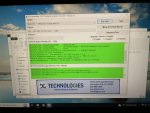
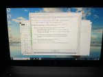
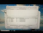
halleluia. Installed twice, then a third time; obvious ineptness. Still no J1939, though J1708 worked:

IMG_3007.jpeg

IMG_3006.jpeg

IMG_3011.jpeg

It looks like I have plenty of issues to learn and investigate here.

Could the transmission codes be related to installing Eco Hubs recently?
 

hike

—realizing each day
Steel Soldiers Supporter
538
849
93
Location
Texas Hill Country
your problem to me seems very clearly a problem between your PC and your adapter. If the PC to DPA connection was good you would get a success message for that and a failure in the VDA to Vehicle window.. I would not be looking at your truck as the source of the problem at this time.

View attachment 909159

I would go back over your USB serial settings (watch youtube for help) and uninstall the dearborn software completely and try again.. You really need to be at a point where the DPA3 is showing up on the list, and that will show up there weather you have the actual device connected or not. this feels like a driver issue to me.
Thank you @Lostchain that certainly was one of my issues.

This is still one, too:

IMG_3594.jpeg

IMG_3595.jpeg

No blinky J1939 =/

I have some winter prep to do this weekend around the house, hopefully I will finish that all tomorrow.

I appreciate all the help, persistence, and advice—
 
Last edited:

Lostchain

Well-known member
Steel Soldiers Supporter
285
588
93
Location
Portland, OR
halleluia. Installed twice, then a third time; obvious ineptness. Still no J1939, though J1708 worked:

View attachment 909161

View attachment 909162

View attachment 909163

It looks like I have plenty of issues to learn and investigate here.

Could the transmission codes be related to installing Eco Hubs recently?

a quick goog search shows some of those are voltage related, doubt it has anything to do with eco hubs, Mine never threw codes for that. the transmission will go into a relearn process, but that doesn't throw a code and it finishes the adaptive shifting stuff pretty quick.


thats interesting the ABS code is indeed a J1939 data link code.. maybe your bus has a short? i would do the prescribed WABCO test for that code..
1698473211568.png


Def not gonna fix that code farting with wheel sensors LOL

GOOD LUCK!
 

hike

—realizing each day
Steel Soldiers Supporter
538
849
93
Location
Texas Hill Country
Try switching the protocol to J1939 and Click "Run Test" and show screen shot please also try CAN

View attachment 909169
IMG_3605.jpeg

IMG_3604.jpeg

IMG_3603.jpeg

IMG_3602.jpeg

IMG_3601.jpeg


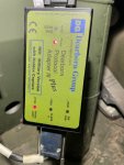
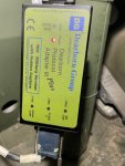
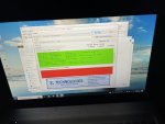
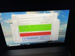
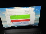
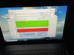
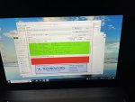
Only J1708 is blinking, which the DPA5 manual states, whether green or red, is the signal that the adaptor is reading the truck side. The adaptor's lights come on and blink whether the computer is connected or not. I am thinking either adaptor or wiring is the next issue to explore?

Perhaps if the Bluefire shows up we can see if it works on J1939—
 

GeneralDisorder

Well-known member
Steel Soldiers Supporter
2,082
5,317
113
Location
Portland, OR
On the diagnostic connector on the truck check the resistance between pins C and D. This should show 120 Ohms - the value of the J1939 bus termination resistor.

If it doesn't, pull the dash panel (gauge panel) and find connector P250/J250 and make sure it's securely plugged together. If it is and you don't have bus termination (120 ohms between C and D) check the termination resistor - follow the wires from J250 and you should find the resistor (R13).... I hope anyway. I haven't looked for it myself but that's where P250/J250 is supposed to live according to the TM.

Since everything on the truck is *working* seemingly (at least well enough to run/drive/fault code) I would assume the various modules present on the bus are at least connected and probably not shorting out the bus or corrupting it - some are obviously responding to the slower bus so my first check would be for proper termination and then go from there.

An inexpensive oscilloscope can be invaluable for looking at CANBUS waveforms. You can get pocket models pretty cheap now. And the CANBUS is only dealing with +/-5v DC and 1 Mbit at the fastest so you don't need anything fancy.
 

hike

—realizing each day
Steel Soldiers Supporter
538
849
93
Location
Texas Hill Country
a quick goog search shows some of those are voltage related, doubt it has anything to do with eco hubs, Mine never threw codes for that. the transmission will go into a relearn process, but that doesn't throw a code and it finishes the adaptive shifting stuff pretty quick.


thats interesting the ABS code is indeed a J1939 data link code.. maybe your bus has a short? i would do the prescribed WABCO test for that code..
View attachment 909170
Thank you. We will keep swinging a the issue(s)—
 

hike

—realizing each day
Steel Soldiers Supporter
538
849
93
Location
Texas Hill Country
On the diagnostic connector on the truck check the resistance between pins C and D. This should show 120 Ohms - the value of the J1939 bus termination resistor.

If it doesn't, pull the dash panel (gauge panel) and find connector P250/J250 and make sure it's securely plugged together. If it is and you don't have bus termination (120 ohms between C and D) check the termination resistor - follow the wires from J250 and you should find the resistor (R13).... I hope anyway. I haven't looked for it myself but that's where P250/J250 is supposed to live according to the TM.

Since everything on the truck is *working* seemingly (at least well enough to run/drive/fault code) I would assume the various modules present on the bus are at least connected and probably not shorting out the bus or corrupting it - some are obviously responding to the slower bus so my first check would be for proper termination and then go from there.
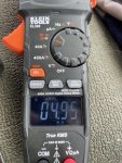
Haven't found a P250/J250 connector as yet. It is not behind the instrument cluster. Found a terminal resistor under the PDP, on a terminal end of P250. I haven't seen J250 anywhere. There are two J1939 cables running off the diagnostic port: 1— J183 to P183; and a huge bundle that appears to take the J1939 cable toward P116. P250 comes back from that bundle. That large bundle splits into P115, P116 at the xtrans ecu?; X21 and two other small bundles that do not connect to anything.

Voltages look good for J1939+ (C) and J1939- (D) according to the Wabco info @Lostchain shared,

IMG_3638.jpeg

IMG_3637.jpeg

but the resistance appears to be off when testing the resistor isolated.

IMG_3649.jpeg


Voltage at the Deutsch connector matches "C" and "D".

IMG_3648.jpeg

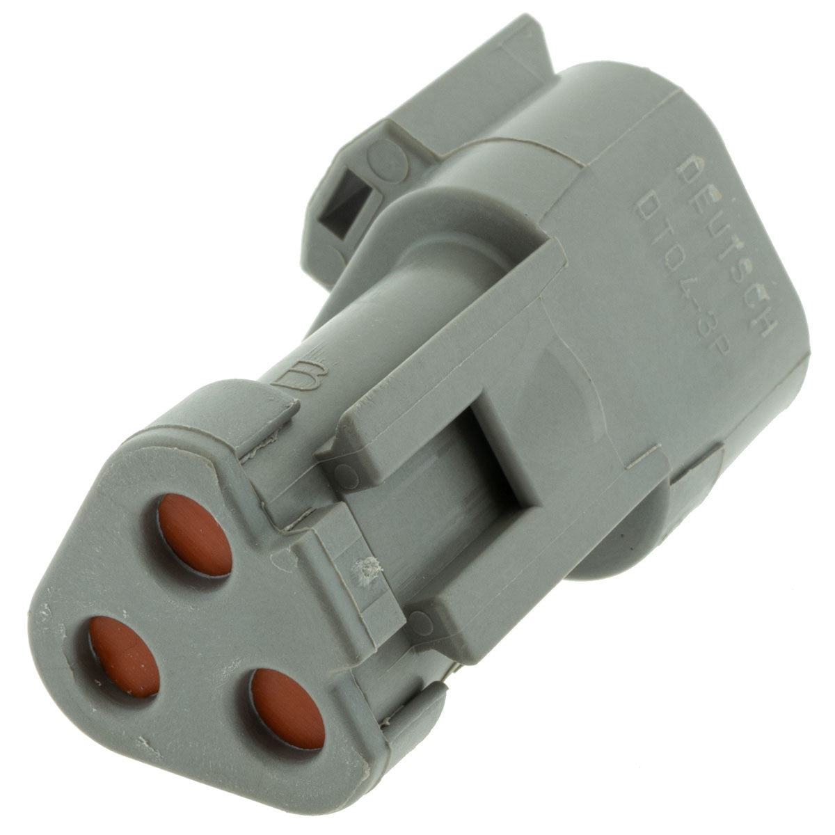
Not sure where to look for a resistor in a DT04-3P connector, nor even the resistor specs.

IMG_3645.jpeg
 

GeneralDisorder

Well-known member
Steel Soldiers Supporter
2,082
5,317
113
Location
Portland, OR
P250 is supposed to be the harness connector for the R13 termination resistor. Does the matching connector show 120 ohms between C and D?

It looked like it would be under the gauge cluster in the TM. But the TM doesn't have the best drawings. But it looks like you found it.
 

hike

—realizing each day
Steel Soldiers Supporter
538
849
93
Location
Texas Hill Country
P250 is supposed to be the harness connector for the R13 termination resistor. Does the matching connector show 120 ohms between C and D?

It looked like it would be under the gauge cluster in the TM. But the TM doesn't have the best drawings. But it looks like you found it.
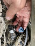
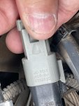
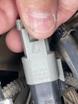
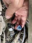
Here is a photo of P250 terminal resistor.

IMG_3645.jpeg

IMG_3648.jpeg
The only P250 label I found was a J1939 wire coming back in a huge bundle from P115, P116, X21, and a couple of 'stringers' unconnected to anything. The P250 terminal end was under the PDP, in the separated space below the circuit board above the footwell where the CTIS manifold and xtran ecu, (P115, P116, P114) appear to be. P250 terminates in this Deutsch DT04-3P connector which I assume has a potted resistor of, to me, unknown specifications.

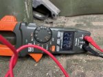
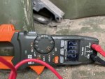
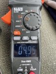
Resistor isolated from circuit, tested at resistor posts.

IMG_3649.jpeg

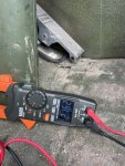
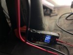
Resistance with the resistor in the powered circuit, tested at "C" and "D".

IMG_3639.jpeg

Resistance with resistor in unpowered circuit, tested at "C" and "D".

IMG_3657.jpeg

I was always taught resistors should be tested outside/isolated from the circuit? Perhaps these are different? I am grateful for the assistance and hoping to learn—
 
Last edited:

Lostchain

Well-known member
Steel Soldiers Supporter
285
588
93
Location
Portland, OR
None of those tests were 60 or 120 Ohms so doesn't that pretty much narrow it down to a bad resistor or am I missing something here?
 

hike

—realizing each day
Steel Soldiers Supporter
538
849
93
Location
Texas Hill Country
None of those tests were 60 or 120 Ohms so doesn't that pretty much narrow it down to a bad resistor or am I missing something here?
Not knowing the proper testing protocol intended for Pvt. Snuffy, nor the specifications of the resistor, beyond 60 or 120 ohms. I can only say 11.5 kOhms may be close. The other tests suggest failed resistor. The isolated test, as we would do for one on a circuit board suggests the resistor is bad. How are the tests intended to be done in this situation? I have found no guidance in the TM's as yet.

Do you have a source for purchasing a new one?
 
Last edited:

GeneralDisorder

Well-known member
Steel Soldiers Supporter
2,082
5,317
113
Location
Portland, OR
You can just use any 1/4 watt 120 Ohm resistor. Jam it into the P250 female terminals and see if she talks.

Meg-Ohm readings or even K-Ohm readings are saying bad resistor to me - 11,500 Ohms is nowhere even close to 120 Ohms..... different universe and not going to work. You can switch the meter off of auto-ranging and it will likely show open circuit. Since you have verified that you have P250 and that the J1939 "+" and "-" are present - stick a 120 Ohm resistor across them. You've got nothing to lose by trying. You have already verified the voltages are within normal ranges. 🤷‍♂️
 

hike

—realizing each day
Steel Soldiers Supporter
538
849
93
Location
Texas Hill Country
You can just use any 1/4 watt 120 Ohm resistor. Jam it into the P250 female terminals and see if she talks.

Meg-Ohm readings or even K-Ohm readings are saying bad resistor to me - 11,500 Ohms is nowhere even close to 120 Ohms..... different universe and not going to work. You can switch the meter off of auto-ranging and it will likely show open circuit. Since you have verified that you have P250 and that the J1939 "+" and "-" are present - stick a 120 Ohm resistor across them. You've got nothing to lose by trying. You have already verified the voltages are within normal ranges. 🤷‍♂️
Right: auto off goes to zero.

Thank you. Thank you. I have been wondering the same most of today, hoping someone else would speak up. I'd prefer to purchase a ready built, though I can source the parts, test, and pot my own once confirmed.

Thank you—
 

GeneralDisorder

Well-known member
Steel Soldiers Supporter
2,082
5,317
113
Location
Portland, OR
I would do an autopsy on the original. Just for giggles. But really a Deutsch DT 3-pin, terminals, wire, and heat shrink is all you need here. No real need to pot it unless you enjoy such exercises. Or you can buy the actual thing if you like:


or


They seem pretty common.
 

hike

—realizing each day
Steel Soldiers Supporter
538
849
93
Location
Texas Hill Country
I would do an autopsy on the original. Just for giggles. But really a Deutsch DT 3-pin, terminals, wire, and heat shrink is all you need here. No real need to pot it unless you enjoy such exercises. Or you can buy the actual thing if you like:


or


They seem pretty common.
I appreciate all the help and even the cajoling. Glad to have the testing kit and will add additional software over time. Would very much like more information about our unit. The -20's [1998, before the A1] don't have items like the ABS brakes, so where did you find the specifications for the resistor? My schematics [2008] only show it, though no specifics. Our -24P [1998] of course does not show it, though I did find where it would be shown in the WTEC III Dashboard Cable Assembly and Power Distribution Panel drawings, which would have led me directly under the PDP, instead of opening all the dash looking for it, (I did confirm I have a 'new' style fan switch [broken] in the heater and got the part numbers for my leaking Haldex service and trailer valves).

While not having the information is encouraging a lot of exploration (farting around as @Lostchain said). Are there copies of the newer digital TM's available to access somewhere? Or do you just have a great notebook collected over the years?
 
Last edited:

aw113sgte

Well-known member
Steel Soldiers Supporter
692
1,058
93
Location
La Crosse, WI
I appreciate all the help and even the cajoling. Glad to have the testing kit and will add additional software over time. Would very much like more information about our unit. The -20's (1998, before the A1) don't have items like the ABS brakes, so where did you find the specifications for the resistor? My schematics (2008 only show it, though no specifics. Our -24P (1998 of course does not show it, though I did find where it would be shown in the WTEC III Dashboard Cable Assembly and Power Distribution Panel drawings, which would have led me directly under the PDP, instead of opening all the dash looking for it, (of course I did confirm I have a 'new' style fan switch [broken] in the heater and got the part numbers for my leaking Haldex service and trailer valves).

While not having the information is encouraging a lot of exploration (farting around as @Lostchain said). Are there copies of the newer digital TM's available to access somewhere? Or do you just have a great notebook collected over the years?
PMd you regarding digital TMs
 

GeneralDisorder

Well-known member
Steel Soldiers Supporter
2,082
5,317
113
Location
Portland, OR
The resistor spec is something I know from dealing with CANBUS in general - my CAT ECM bench flash cable had to have a termination resistor added..... the 120 Ohm rating is sometimes shown in the schematic and sometimes not but I didn't look at a manual for that information. I'm sure buried in the troubleshooting steps somewhere they will have soldier A check the resistance through it but it won't describe why they are testing it.

PM me if you want to discuss electronic TM's and such. That's a whole other topic.
 

Lostchain

Well-known member
Steel Soldiers Supporter
285
588
93
Location
Portland, OR
The resistor spec is something I know from dealing with CANBUS in general - my CAT ECM bench flash cable had to have a termination resistor added..... the 120 Ohm rating is sometimes shown in the schematic and sometimes not but I didn't look at a manual for that information. I'm sure buried in the troubleshooting steps somewhere they will have soldier A check the resistance through it but it won't describe why they are testing it.

PM me if you want to discuss electronic TM's and such. That's a whole other topic.
@hike
Once you have the TMs
I did see a “troubleshooting data bus” procedure in the TM and it will step you through the process taking readings from your truck, using the ICE box that came with your kit.
 
Top
AdBlock Detected

We get it, advertisements are annoying!

Sure, ad-blocking software does a great job at blocking ads, but it also blocks useful features of our website like our supporting vendors. Their ads help keep Steel Soldiers going. Please consider disabling your ad blockers for the site. Thanks!

I've Disabled AdBlock
No Thanks