• Steel Soldiers now has a few new forums, read more about it at: New Munitions Forums!

  • Microsoft MSN, Live, Hotmail, Outlook email users may not be receiving emails. We are working to resolve this issue. Please add support@steelsoldiers.com to your trusted contacts.

Curious old M49 fuel truck

msgjd

Well-known member
1,118
3,461
113
Location
upstate ny
Not sure if you are referring to the centerline of the PTO output shaft? If so, the offset is less than 1/2", actually.
yes i was .. thank you for the correction !!! and post has been edited.. Been 3 years since i looked at backside of the "stripped" truck and i was 122 miles away from it when doing the post.. my pictures make it look more offset and today i was home and yep, just a whisker offset as you say .. thanks again for pointing that out promptly ;)
 
Last edited:

msgjd

Well-known member
1,118
3,461
113
Location
upstate ny
I have three questions for people who know "the real thing"
Any help here would be greatly appreciated.
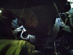
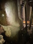
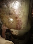
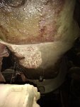
Just a note that the pics Valley Rock might be posting for you of his stainless tanks are inapplicable to the gasser 1951-1963 three-compartment steel tanked M49C you wish to model , as the early steel tanks are very different from the later stainless or aluminum tanks ..

At quick glance they look similar but they have their own differences.. It would be good for him to post them so others can see the differences through the ages, but I just needed to put this tidbit here to head off any future confusion
 
Last edited:

Paweł

Well-known member
75
254
53
Location
Poland
Hello!
I've just finished my V100 model - you can see it here:

Now I started working on my first deuce.

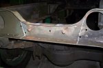
I cleaned up the frame rails and I made new grabhandles, to match the ones from @msgjd 's photos - the kit ones are different:


Now I would like to move on, but I'm not sure about some things... Let me show you:


What would be A61? Does it look OK for a gasser M49? How about A22 - it looks suspicious to me. I'd like to hear your comments here to correct the parts where necessary.

Thanks in advance and have a nice day

Paweł
 

msgjd

Well-known member
1,118
3,461
113
Location
upstate ny


What would be A61? Does it look OK for a gasser M49? How about A22 - it looks suspicious to me. I'd like to hear your comments here to correct the parts where necessary.
I concur with HDN about A61 being the booster.. Piece A22 is strange, yes there's a crossmember in that location on the real gassers, however I don't think mine has a perpendicular section on it as seen above.. You have me curious now, I will have to look at the truck again when I get home next week .. Also, the real tanks sit on a pair of U-channel brackets bolted to the frame rails, which you will see in a couple of my pictures earlier in this post
 
Last edited:

Paweł

Well-known member
75
254
53
Location
Poland
Hello everybody!
Thanks a lot for your great help.
@HDN - thanks, now I know what to look for.
@msgjd - thanks for your comment, I'd love to see some more pictures from your truck
@gringeltaube - thanks a lot, I love that picture, it's a great reference!

I'm currently scratchbuilding that crossmember forward of the transfer case. Looks like I'll also have to scrachbuild the front motor mount crossmember. The kit supplied part seems to be OK for a multifuel-powered truck, how about a gasser - the front crossmember was different, right?

Maybe I can also put together the rears, let's see. Thanks again for your great help and have a nice day

Paweł
 

gringeltaube

Staff Member
Super Moderator
Moderator
Steel Soldiers Supporter
7,005
2,619
113
Location
Montevideo/Uruguay
I'm currently scratchbuilding that crossmember forward of the transfer case. Looks like I'll also have to scrachbuild the front motor mount crossmember.
They both are basically the same shape/profile as all others. Exception would be that Ø4.0" hole for the winch DS, to the left of the front one.
 

Attachments

Paweł

Well-known member
75
254
53
Location
Poland
Merry Christmas everybody!

@gringeltaube - thanks again, that picture helps a lot, I'm scratchbuilding that crossmember right now!


Assembling the axles I made sure to put the whole thing on an even surface, to prevent some of the wheels from hanging in the air later:


chassis03.jpg


As you can see I have scratchbuilt a new frame crossmember under the cab to show the mounting of the transfer case right. You can also see the new front crossmember under construction. I have also filled the holes in the air tanks to mount them like in the pictures of the real thing above. The transfer case from the kit had really bad sink holes in its mounts.

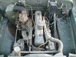
The engine itself is simplified in the kit and I think I’ll stick with this solution, but I’ll have to rework it a little, to show the gas engine. Now it looks like this:

chassis04.jpg


I filled the ejector pin marks and I closed up the hole in the fender for the exhaust stack. From what I see I’ll have to make a new oil pan and maybe this will be enough. I also understand that I have to rework the louvers on the fenders, right?

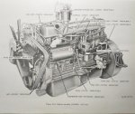
Here again a big request for help - could I ask for some more pictures of the underside of the gas engine? This would the the 331 golden comet, right? Could I ask you to take rough measurements of the oil pan (width and length)?

Thanks for looking and thanks in advance for any help I might get here! Have a nice day

Paweł
 

msgjd

Well-known member
1,118
3,461
113
Location
upstate ny
From what I see I’ll have to make a new oil pan and maybe this will be enough. I also understand that I have to rework the louvers on the fenders, right?

Here again a big request for help - could I ask for some more pictures of the underside of the gas engine? This would the the 331 golden comet, right? Could I ask you to take rough measurements of the oil pan (width and length)?

Thanks for looking and thanks in advance for any help I might get here! Have a nice day

Paweł
correct, you will have to change the louvers, the oil pan, and possibly the oil filter can etc... I will be home again on 27Dec and get you some pics and measurements
 

gringeltaube

Staff Member
Super Moderator
Moderator
Steel Soldiers Supporter
7,005
2,619
113
Location
Montevideo/Uruguay
.... could I ask for some more pictures of the underside of the gas engine? This would the the 331 golden comet, right? Could I ask you to take rough measurements of the oil pan (width and length)?
I have many of these engines here, so you can have every measurement you want. (just not today - because I will have to dig in the junk pile, to get at least one freed... :wink:)

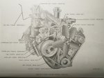
Now, here is something to start with, at least....
 

Attachments

Paweł

Well-known member
75
254
53
Location
Poland
Hello everybody!
My best greetings for you in the new year - I wish you good health and lots of fun with your machines!

I'm slowly workin' on my model. Here's what I have so far:


I have installed the air tanks to match the @msgjd 's photos, finished the transfer case installation, installed the shafts for the rears and the rear crossmember. The motor mount crossmember is also ready to be installed, I'm just not so sure on its exact position. That's why I would like to respectfully ask for your help once again. Also, If I had the rough measurements of the oil pan, I could tackle the underside of the engine.

One more thing that I would like to ask - I noticed that the early deuces were built so that the headlights were "low". Then at some point the assembly around the radiator got turned around and from then on the headlights are mounted "high". Can you please tell me when did this change happened and what was the thought behind it? I'd also like to know if the truck I'm building would be more correct with the headlights "high" or "low". I personally like the looks of the "high" headlights better.

Thanks in advance and have a nice day!

Paweł
 

msgjd

Well-known member
1,118
3,461
113
Location
upstate ny
One more thing that I would like to ask - I noticed that the early deuces were built so that the headlights were "low". Then at some point the assembly around the radiator got turned around and from then on the headlights are mounted "high". Can you please tell me when did this change happened and what was the thought behind it? I'd also like to know if the truck I'm building would be more correct with the headlights "high" or "low". I personally like the looks of the "high" headlights better.
Paweł
if your model is going to have a front winch, the headlights should be upper ("high") quadrant .. This was done so the winch did not interfere with the headlight beams.. I am unsure whether this logic was applied to all winch trucks by the various builders because I had a 1954 Studebaker M108 gas wrecker with winch yet it had low-quadrant headlights, against the logic.. I have no idea if it had come that way or if they got flipped during its lifetime..

All non-winch gassers within the 2.5T M44-series had lower quadrant headlights when built..

Of the gassers that eventually received multifuel engines later on, this feature remained unchanged on many of them, although there's a number of them that returned from rebuilding with quadrants flipped to upper quadrant, perhaps an attempt to standardize (visually match) the as-built multifuel trucks they would be working with .. Yes, this means all the original factory-built multifuels from their inception in 1964 and thereafter have upper quadrant headlights, regardless of a winch or not

The "flip" is performed by unbolting the two rectangular narrow panels on each side of the radiator support , rotating them 180-degrees of course, and moving the three lamp assemblies to their new locations
 

gringeltaube

Staff Member
Super Moderator
Moderator
Steel Soldiers Supporter
7,005
2,619
113
Location
Montevideo/Uruguay
The motor mount crossmember is also ready to be installed, I'm just not so sure on its exact position.
Distance btw it (EE) and the next one (Z) is 6ft, exactly.
Also, If I had the rough measurements of the oil pan, I could tackle the underside of the engine.
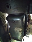
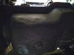
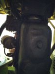
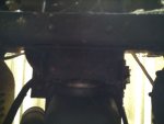
The engine block is about 32in long x 13in wide and the oil pan measures 29" x 10" x 5" (rear half) x 9" (front half = deep sump).
Its mounting flange is 1.25" wide. There is a 5"x2" hump on the drivers side, which can be seen in this picture.

Pics were shot while crawling around in the dirt trying to avoid critters and greasy axle parts, so not the best quality...
 

Attachments

Paweł

Well-known member
75
254
53
Location
Poland
@msgjd , @gringeltaube - thanks a lot for the cool infos!

So I'll have to mount the headlights low - that will make my model look original!

Thanks for the measurements and for the pics - I really appreciate your crawling under! I'll try to build some representation of the 331 engine underside. I'll post pictures when I have something.

Thanks again and have a nice day!

Paweł
 

Paweł

Well-known member
75
254
53
Location
Poland
Hello everybody!

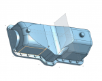
I thought before cutting and gluing anything I'd make a quick drawing in 3D to sort everything out... Now I think maybe it would be good to just 3D print the part... Here's what it looks like:

1736024536544.png

One thing that I don't feel yet is the exact way the motor mounts to the front crossmember...

If I may, I would also like to ask for a few more pics of the louvers under the fenders to see what I have to change in the fenders from the kit.

Thanks again for your great help, have a nice day

Paweł
 
Top
AdBlock Detected

We get it, advertisements are annoying!

Sure, ad-blocking software does a great job at blocking ads, but it also blocks useful features of our website like our supporting vendors. Their ads help keep Steel Soldiers going. Please consider disabling your ad blockers for the site. Thanks!

I've Disabled AdBlock
No Thanks