• Steel Soldiers now has a few new forums, read more about it at: New Munitions Forums!

  • Microsoft MSN, Live, Hotmail, Outlook email users may not be receiving emails. We are working to resolve this issue. Please add support@steelsoldiers.com to your trusted contacts.

12 volt towing box

rustystud

Well-known member
9,280
2,988
113
Location
Woodinville, Washington
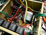
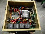
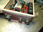
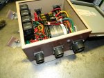
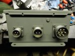
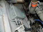
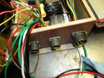
Well I'm one step closer to my "Alaskan Adventure" . I finished the 12 volt towing box for my travel trailer. Now my deuce can tow any 12 volt trailer. Just plug it in and go. I have both the "7 pin Flat (RV) style" and "7 pin round (commercial) style" plugs. Plus the original 24 volt connector.
002.jpg004.jpg006.jpg009.jpg011.jpg012.jpg010.jpg016.jpg

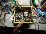
This box controls everything. It has inputs from the "brake controller" on the dash to the turn signals and taillights and a signal from the air-pac for the stop lights.
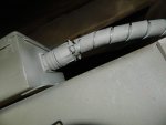
The cable that goes to the back of the truck is a "10-gauge 7 wire cable" that is wrapped in a "nylon" sleave and then goes into a 1" PVC pipe that is clamped to the frame. The power inputs are 12 volt from the auxiliary battery and are #4 cable. Also there is the reverse signal from the nifty switch I got from "Peashooter" !
All connections are crimped, then soldered, then heat shrink wrapped. I have a spare "light module" and of course spare fuses. I made it so that if the light module goes bad I can simply change it out by just unscrewing the screws on the junction strip.
 
Last edited:

clinto

Moderator, wonderful human being & practicing Deuc
Staff member
Administrator
Super Moderator
Steel Soldiers Supporter
Supporting Vendor
12,596
1,132
113
Location
Athens, Ga.
I love this and it's really well done. It mirrors something I'm currently building for myself.

Where did you get the cannon connectors?
 

Speedwoble

Well-known member
606
301
63
Location
New Holland, PA
Looks beautiful. Nicely done.
Personally I never soldier wires on vehicles as the solder makes them more likely to crack, the reason OEM’s do not solder connections. However the use of heat shrink will help support the wires and reduce this.
 

rustystud

Well-known member
9,280
2,988
113
Location
Woodinville, Washington
Looks beautiful. Nicely done.
Personally I never soldier wires on vehicles as the solder makes them more likely to crack, the reason OEM’s do not solder connections. However the use of heat shrink will help support the wires and reduce this.
This is not true. I debunked this "Urban" myth a few years ago. Here is a paper I just had on my desk from Delco-Remy. It clearly says to "solder" the connections. I posted a paper from "NASA" saying how to properly solder the connections for all the space vehicle's. Now if something is going to be "shaking a connection" a space vehicle clearly fits that Bill ! What causes the problem is "improper" soldering techniques. If you let the solder flow down the wire, especially under the plastic covering then it can become brittle. Stop and think for a moment. The connector your using is usually made from solid copper and tin coated. It doesn't break does it ? Yet it is "solid" . Now soldering the wire to that connector will make it just as solid as that connector. Nothing more. According to those people who say it makes them too solid, what do they have to say about that ? Solid is solid. Someone always comes back with "then why doesn't the vehicle manufactures solder their connections ?" . The answer is "they do" on critical connections. For the rest of the connections a simple crimp works fine for the average life expectancy of a vehicle. So why would they spend all that extra money when they don't have to. No, this is a myth that has been going around to long now.

View attachment Scan0234.pdf

Here's a great article on connecting wires. http://www.musclecardiy.com/automot...motive-electrical-connections-and-connectors/
 
Last edited:

rustystud

Well-known member
9,280
2,988
113
Location
Woodinville, Washington
Looks great! Are those relays or step down transformers?
also, what do you estimate the cost at?
There 24 volt relays. I have a dedicated 12 volt supply in and the signals from the truck are all 24 volt. So I use the trucks signals (turn lights, brake lights, taillights) to activate the relays and that supplies my 12 volts for the trailer.
 

41cl8m5

Active member
254
36
28
Location
Littleton, CO
Rustystud, great job on this. It does look like something the military machine would come up with to adapt to a vehicle that did not have this function, probably the cost would be a heck of a lot more than you put into it, thanks for sharing this with the community. I was wondering what is the limit of the amp draw on the individual 12v circuits?
 

rustystud

Well-known member
9,280
2,988
113
Location
Woodinville, Washington
Rustystud, great job on this. It does look like something the military machine would come up with to adapt to a vehicle that did not have this function, probably the cost would be a heck of a lot more than you put into it, thanks for sharing this with the community. I was wondering what is the limit of the amp draw on the individual 12v circuits?
I ran 10 gauge wire from the "box" to the trailer connection. Each circuit is protected with a 20 amp breaker except the electric brakes which has a "automatic reset breaker" that is 30 amps.
I suppose I should show the "junction" box in the back that splits the circuit to the two trailer connectors. One is a 7 way Blade RV style. The other is a 7 way pin "commercial" connector. All are connected with military style Amphenol connectors.
I'll take some pictures tomorrow if it doesn't rain.
 

rustystud

Well-known member
9,280
2,988
113
Location
Woodinville, Washington
003.jpg

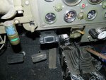
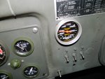
Here's a picture of my brake controller. It can handle a 3 axle trailer.

004.jpg

I always test the brakes whenever I get in the cab. Just a habit. 500 Ibs is where it is suppose to be. I have gotten it up to almost 600 Ibs once. I had to grab a hold of the steering wheel and push for all I was worth though. Of course if I started up the truck and built up some air pressure, the gauge would be over 800 Ibs just by looking at the brake pedal ! With air pressure and pushing hard, the gauge reads over 2000 Ibs pressure.
 
Last edited:

rustystud

Well-known member
9,280
2,988
113
Location
Woodinville, Washington
001.jpg002.jpg003.jpg

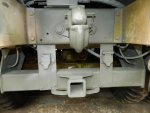
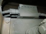
I finally got out and took some pictures of the trailer connectors and junction box. The junction box has just a simple 6 connector strip and a ground stud inside. I soldered the wire connectors on and put heat shrink on them. Then screwed them down to the connector strip. Connecting all right turn signal wires together and all left turn signal wires together etc... Simple. I went this way so that in the future if I change my mind about the style of connectors I'm using, I can change them out real easy.
As it is, the left one is the 7 pin (commercial) style, and the right one is the 7 blade (RV) style. Both are 12 volt. I still have the original 24 volt one for my M105 trailer.
 
Top
AdBlock Detected

We get it, advertisements are annoying!

Sure, ad-blocking software does a great job at blocking ads, but it also blocks useful features of our website like our supporting vendors. Their ads help keep Steel Soldiers going. Please consider disabling your ad blockers for the site. Thanks!

I've Disabled AdBlock
No Thanks