• Steel Soldiers now has a few new forums, read more about it at: New Munitions Forums!

  • Microsoft MSN, Live, Hotmail, Outlook email users may not be receiving emails. We are working to resolve this issue. Please add support@steelsoldiers.com to your trusted contacts.

12k shock mod (Softer Ride)

kromby

New member
5
19
3
Location
MA
I have an ECV M1114, cast rear upper spring mounts, non progressive rear springs. I had trouble driving it over 2MPH off road and wouldn't take it on some of the bad roads around town because it was so rough. Per some other threads I pulled the shocks completely for a few miles, rode much much better, definitely over sprung but hitting some bumps, rocks and dirt wasnt bad at all. This took care of the bumps but it was way too bouncy, unsafe above 30MPH on slow deep whoop style bumps, felt ready to head into orbit. Also the un-damped dual spring with center mass system caused some issues too.

I almost went with the Cepek shocks but was worried the compression damping would be too much and wanted to try and keep the stock springs so I decided to see what could be done with the stock shocks. I am also designing some new suspension on another car so I wanted to see if I could apply anything here.

I picked up a set of 4 new 12k shocks (Rear ECV shocks are actually shorter with external bump stop but the total length extended/collapsed was the same so I put the 12K's on all 4 corners) and practiced on my two original front shocks. I made the modifications and put them back together and am very pleased with the performance. I did not dyno these shocks before or after nor did I get corner weights on the truck. The modifications may increase cavitation/aeration in the shock oil so time will tell if they hold up. I will probably end up going with a new combo before that happens anyway. This info is intended for information only.

The shocks are a standard twin tube design, oil filled. They are not gas charged and with no gas bag, so no worries opening them. The majority of the compression resistance is from an unbelievably tiny orifice in the base valve. The majority of the low-mid speed rebound resistance looks to be from a stiff (spring managed) main piston valve with the higher speed resistance added by a two stage base valve. (Im not an expert these are assumptions from observations)

Tools needed (Minimum), removal not covered:
-Angle grinder (I used a chop saw also)
-1 1/8 socket
-7/8 wrench
-New shock oil if desired (I used 2.5W)
-Tig welder (Or a friend with one)

Procedure
-Grind open the outer shock body
-Disassemble the piston stack
-Drill 4 holes in the piston
-Bevel 3 of the holes
-Drill one hole in the base valve
-Clean
-Add shock oil (Or filtered original oil)
-Resemble (Make sure EVERYTHING is in the proper order and orientation)
-Weld shut

I am in ~150 USD for four new-modified shocks.

To disassemble the shock I put the shock body in my chop saw and carefully rotated it until I removed the majority of the crimp on top and just a drop of oil came out. I touched up the remainder of the spots with an angle grinder. A lathe would have been much better but I dont have one and didnt want to sink any money into the project as I didnt know how it would pan out.
Dont cut all the way through as the outer shock body top hat extends below the crimp so as long as the crimped part is removed it is easy to slide back together and weld up.
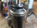
20240919_091551.jpg
I put a bar through the upper eye and tapped up until the upper hat popped off.
I slooooooooowly (Very slowly) lifted the assembly up, this left the inner shock tube inside of the shock body and the shaft/piston came out. If you lift up too fast the inner shock body will come out too, fall off, drop back into the shock body and splash all the oil into your face (How do I know)

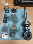
The guts:
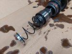
20240904_135230.jpg
Left -> Right:
1) Compression bump stop valve (silver) (This plugs the base valve when it gets down far enough)
2) Compression bump stop spring
3) Compression bump stop nut
4) Rebound valve/shim stack nut (Covered here)
5) Rebound valve/shim stack spring (Compressed here)
6) Shock piston (Largest diameter silver piece)
7) Compression spring retainer (Right above the shock piston)
8) Extension bump stop (This fits inside the upper inner shock tube hat and meters fluid at full extension, only about 1/4" of stroke)
9) Inner shock tube hat

When disassembling (After the compression bump stop nut is removed) the rebound shim stack spring retainer can be removed with a 1 1/8 socket. There is preload here but the spring will fully relax before the retainer runs out of thread so it can just be zipped off:
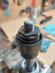
20240919_092330.jpg

Disassembled:
20240919_092843.jpg
Top -> Bottom, left to right:
1) Compression bump stop valve (silver) (This plugs the base valve when it gets down far enough)
2) Compression bump stop spring
3) Compression bump stop nut
4) Rebound valve/shim stack nut
5) Rebound valve/shim stack spring
6) Rebound valve spring nut shim (helps set spring preload)
7) Rebound valve/shim stack spring seat
8 ) Rebound valve shim stack (My shock had 3 shims, lowest shim had a cut out in it, presumably for low speed rebound)
9) Shock piston
10) Compression valve (No shims here)
11) Compression valve spring.
12) Compression spring retainer (Right above the shock piston)
13) Extension bump stop (This fits inside the upper inner shock tube hat and meters fluid at full extension, only about 1/4" of stroke)
14) Inner shock tube hat.

My inner shock tube hat was stuck inside the outer tube top. I pried it out of the ones it didn't fall out of. This makes assembly easier. It may pop out from the shaft seal retainer spring.

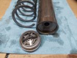
Inner shock tube view from the bottom. This is the shock base valve as well
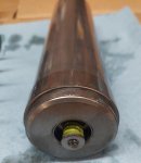
20240919_092124.jpg

To disassemble this place it in a vice (Loosely so the lower portion can be pressed out):
you can see the lip is supported by the vice but the smaller diameter valve can be pressed out
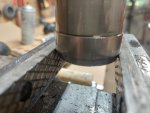
20240919_092919.jpg

I used a small deep socket and some extensions to get in there to hammer it out from the top:
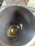
20240919_092958.jpg
20240919_093005.jpg

Here is the base valve hammered out:
20240919_093214.jpg

The base valve hole is the key. The base valve is why the compression is sooo stiff on these shocks. On rebound the 4 fingers let the star shaped piece inside push up letting fluid back into the inner body. The smaller inner piece opens under even higher shaft velocities. BUT under compression there is only two tiny nicks in the valve seat, cant be more than 1/32 total so as the shaft enters the shock it takes a tremendous amount of force to move fluid through the base valve making the shock unbelievably stiff. The compression spring on the main piston is so light that it does "nothing" the fluid just pours right out (Especially after more holes are added).

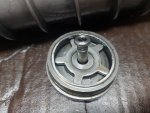
I couldn't find a way to disassemble the base valve without breaking the springs but it was not needed but a cut one is shown below:
20240905_210129.jpg

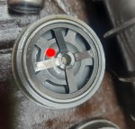
I drilled a 1/8" hole in the base valve in the following location (Red):
20240905_210308.jpg

I drilled x3 1/8" holes FROM THE TOP in the piston on the outer ring (The drill direction is very important or you could drill through a valve seat on the opposite side (The raised rings)). These 3 holes decrease compression resistance on the main piston in the following locations (Red). There is one additional 1/8 hole drilled for rebound this must be done FROM THE BOTTOM for the same reason.
20240919_092641.jpg
This gives 4 holes total for compression (Outer ring) and 3 holes for rebound (Inner ring). I also enlarged the two existing rebound holes to 1/8" as well.

I beveled the bottom side of the compression bleed holes and added a small cutout (Circled in red) in the rebound valve seat to allow for more low speed bleed before the valve opened.
20240919_101732.jpg

This cut out was to increase the cutout capacity of the 1st shim in the rebound stack. The shim is shown placed on the piston. It can be seen that the slot extends inside of the valve seat allowing some low speed bleed.
20240919_092815.jpg

After the holes are drilled, re-assemble everything and add about 380mL of shock oil. I chose 2.5W from summit. My guess is that the original oil is 5w.
All this work was done in a "clean" environment and re-assembly was kept as clean as possible. Any grit or dirt in the shim stack can stick the valve open, mar the piston, change the spring preload etc.

After the 1st shock I had all 4 rebuilt in about 3hrs. Getting them shut again was tricky, I put a socket under the top shock eye so I could push down on the shock shaft to compress the shaft seal spring. I used a hammer to tap the outer shock body top back into the lower outer shock body. Friction kept it together and I tacked it shut.

The welding was tricky, I TIG'ed it only about 1/4" at a time, cooled it down with a damp rag and went to the other side. This took about 2 hrs so I didnt melt the shaft seal.

The shock compresses to the bump stop but I cant get it down that far, here is the front right on a rock (Right rear is off the ground):
20240923_134838.jpg

With some lighter springs I could probably get another 2-3 in of travel.

The rig is much more pleasurable to drive, most road bumps are much much softer (not the big ones though, its not a caddi) and off road is much improved, still slow going but much faster. This did not (For me) completely solve the high spring rate/oversprung ride. I will probably move to a softer spring down the road but the shock mod goes a long way. Time will tell if they hold up but so far so good and worth <$200.
 
Last edited:

TOBASH

Father, Surgeon, Cantankerous Grouch
Steel Soldiers Supporter
Supporting Vendor
3,582
3,491
113
Location
Brooklyn, NY
I have an ECV M1114, cast rear upper spring mounts, non progressive rear springs. I had trouble driving it over 2MPH off road and wouldn't take it on some of the bad roads around town because it was so rough. Per some other threads I pulled the shocks completely for a few miles, rode much much better, definitely over sprung but hitting some bumps, rocks and dirt wasnt bad at all. This took care of the bumps but it was way too bouncy, unsafe above 30MPH on slow deep whoop style bumps, felt ready to head into orbit. Also the un-damped dual spring with center mass system caused some issues too.

I almost went with the Cepek shocks but was worried the compression damping would be too much and wanted to try and keep the stock springs so I decided to see what could be done with the stock shocks. I am also designing some new suspension on another car so I wanted to see if I could apply anything here.

I picked up a set of 4 new 12k shocks (Rear ECV shocks are actually shorter with external bump stop but the total length extended/collapsed was the same so I put the 12K's on all 4 corners) and practiced on my two original front shocks. I made the modifications and put them back together and am very pleased with the performance. I did not dyno these shocks before or after nor did I get corner weights on the truck. The modifications may increase cavitation/aeration in the shock oil so time will tell if they hold up. I will probably end up going with a new combo before that happens anyway. This info is intended for information only.

The shocks are a standard twin tube design, oil filled. They are not gas charged and with no gas bag, so no worries opening them. The majority of the compression resistance is from an unbelievably tiny orifice in the base valve. The majority of the low-mid speed rebound resistance looks to be from a stiff (spring managed) main piston valve with the higher speed resistance added by a two stage base valve. (Im not an expert these are assumptions from observations)

Tools needed (Minimum), removal not covered:
-Angle grinder (I used a chop saw also)
-1 1/8 socket
-7/8 wrench
-New shock oil if desired (I used 2.5W)
-Tig welder (Or a friend with one)

Procedure
-Grind open the outer shock body
-Disassemble the piston stack
-Drill 4 holes in the piston
-Bevel 3 of the holes
-Drill one hole in the base valve
-Clean
-Add shock oil (Or filtered original oil)
-Resemble (Make sure EVERYTHING is in the proper order and orientation)
-Weld shut

I am in ~150 USD for four new-modified shocks.

To disassemble the shock I put the shock body in my chop saw and carefully rotated it until I removed the majority of the crimp on top and just a drop of oil came out. I touched up the remainder of the spots with an angle grinder. A lathe would have been much better but I dont have one and didnt want to sink any money into the project as I didnt know how it would pan out.
Dont cut all the way through as the outer shock body top hat extends below the crimp so as long as the crimped part is removed it is easy to slide back together and weld up.
View attachment 932160
I put a bar through the upper eye and tapped up until the upper hat popped off.
I slooooooooowly (Very slowly) lifted the assembly up, this left the inner shock tube inside of the shock body and the shaft/piston came out. If you lift up too fast the inner shock body will come out too, fall off, drop back into the shock body and splash all the oil into your face (How do I know)

The guts:
View attachment 932161
Left -> Right:
1) Compression bump stop valve (silver) (This plugs the base valve when it gets down far enough)
2) Compression bump stop spring
3) Compression bump stop nut
4) Rebound valve/shim stack nut (Covered here)
5) Rebound valve/shim stack spring (Compressed here)
6) Shock piston (Largest diameter silver piece)
7) Compression spring retainer (Right above the shock piston)
8) Extension bump stop (This fits inside the upper inner shock tube hat and meters fluid at full extension, only about 1/4" of stroke)
9) Inner shock tube hat

When disassembling (After the compression bump stop nut is removed) the rebound shim stack spring retainer can be removed with a 1 1/8 socket. There is preload here but the spring will fully relax before the retainer runs out of thread so it can just be zipped off:
View attachment 932165

Disassembled:
View attachment 932166
Top -> Bottom, left to right:
1) Compression bump stop valve (silver) (This plugs the base valve when it gets down far enough)
2) Compression bump stop spring
3) Compression bump stop nut
4) Rebound valve/shim stack nut
5) Rebound valve/shim stack spring
6) Rebound valve spring nut shim (helps set spring preload)
7) Rebound valve/shim stack spring seat
8 ) Rebound valve shim stack (My shock had 3 shims, lowest shim had a cut out in it, presumably for low speed rebound)
9) Shock piston
10) Compression valve (No shims here)
11) Compression valve spring.
12) Compression spring retainer (Right above the shock piston)
13) Extension bump stop (This fits inside the upper inner shock tube hat and meters fluid at full extension, only about 1/4" of stroke)
14) Inner shock tube hat.

My inner shock tube hat was stuck inside the outer tube top. I pried it out of the ones it didn't fall out of. This makes assembly easier. It may pop out from the shaft seal retainer spring.

Inner shock tube view from the bottom. This is the shock base valve as well
View attachment 932167

To disassemble this place it in a vice (Loosely so the lower portion can be pressed out):
you can see the lip is supported by the vice but the smaller diameter valve can be pressed out
View attachment 932168

I used a small deep socket and some extensions to get in there to hammer it out from the top:
View attachment 932170
View attachment 932171

Here is the base valve hammered out:
View attachment 932172

The base valve hole is the key. The base valve is why the compression is sooo stiff on these shocks. On rebound the 4 fingers let the star shaped piece inside push up letting fluid back into the inner body. The smaller inner piece opens under even higher shaft velocities. BUT under compression there is only two tiny nicks in the valve seat, cant be more than 1/32 total so as the shaft enters the shock it takes a tremendous amount of force to move fluid through the base valve making the shock unbelievably stiff. The compression spring on the main piston is so light that it does "nothing" the fluid just pours right out (Especially after more holes are added).

I couldn't find a way to disassemble the base valve without breaking the springs but it was not needed but a cut one is shown below:
View attachment 932181

I drilled a 1/8" hole in the base valve in the following location (Red):
View attachment 932185

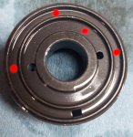
I drilled x3 1/8" holes FROM THE TOP in the piston on the outer ring (The drill direction is very important or you could drill through a valve seat on the opposite side (The raised rings)). These 3 holes decrease compression resistance on the main piston in the following locations (Red). There is one additional 1/8 hole drilled for rebound this must be done FROM THE BOTTOM for the same reason.
View attachment 932186
This gives 4 holes total for compression (Outer ring) and 3 holes for rebound (Inner ring). I also enlarged the two existing rebound holes to 1/8" as well.

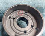
I beveled the bottom side of the compression bleed holes and added a small cutout (Circled in red) in the rebound valve seat to allow for more low speed bleed before the valve opened.
View attachment 932187

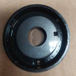
This cut out was to increase the cutout capacity of the 1st shim in the rebound stack. The shim is shown placed on the piston. It can be seen that the slot extends inside of the valve seat allowing some low speed bleed.
View attachment 932188

After the holes are drilled, re-assemble everything and add about 380mL of shock oil. I chose 2.5W from summit. My guess is that the original oil is 5w.
All this work was done in a "clean" environment and re-assembly was kept as clean as possible. Any grit or dirt in the shim stack can stick the valve open, mar the piston, change the spring preload etc.

After the 1st shock I had all 4 rebuilt in about 3hrs. Getting them shut again was tricky, I put a socket under the top shock eye so I could push down on the shock shaft to compress the shaft seal spring. I used a hammer to tap the outer shock body top back into the lower outer shock body. Friction kept it together and I tacked it shut.

The welding was tricky, I TIG'ed it only about 1/4" at a time, cooled it down with a damp rag and went to the other side. This took about 2 hrs so I didnt melt the shaft seal.

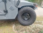
The shock compresses to the bump stop but I cant get it down that far, here is the front right on a rock (Right rear is off the ground):
View attachment 932189

With some lighter springs I could probably get another 2-3 in of travel.

The rig is much more pleasurable to drive, most road bumps are much much softer (not the big ones though, its not a caddi) and off road is much improved, still slow going but much faster. This did not (For me) completely solve the high spring rate/oversprung ride. I will probably move to a softer spring down the road but the shock mod goes a long way. Time will tell if they hold up but so far so good and worth <$200.
Easily one of the best and most exciting reads I’ve seen.

Freakin’ amazing pictures and write up!

Can’t say enough positive words.

This should be a sticky in the hot rods and modifications section.
 
Last edited:

TNDRIVER

Well-known member
Steel Soldiers Supporter
333
508
93
Location
Cleveland,TN
I have an ECV M1114, cast rear upper spring mounts, non progressive rear springs. I had trouble driving it over 2MPH off road and wouldn't take it on some of the bad roads around town because it was so rough. Per some other threads I pulled the shocks completely for a few miles, rode much much better, definitely over sprung but hitting some bumps, rocks and dirt wasnt bad at all. This took care of the bumps but it was way too bouncy, unsafe above 30MPH on slow deep whoop style bumps, felt ready to head into orbit. Also the un-damped dual spring with center mass system caused some issues too.

I almost went with the Cepek shocks but was worried the compression damping would be too much and wanted to try and keep the stock springs so I decided to see what could be done with the stock shocks. I am also designing some new suspension on another car so I wanted to see if I could apply anything here.

I picked up a set of 4 new 12k shocks (Rear ECV shocks are actually shorter with external bump stop but the total length extended/collapsed was the same so I put the 12K's on all 4 corners) and practiced on my two original front shocks. I made the modifications and put them back together and am very pleased with the performance. I did not dyno these shocks before or after nor did I get corner weights on the truck. The modifications may increase cavitation/aeration in the shock oil so time will tell if they hold up. I will probably end up going with a new combo before that happens anyway. This info is intended for information only.

The shocks are a standard twin tube design, oil filled. They are not gas charged and with no gas bag, so no worries opening them. The majority of the compression resistance is from an unbelievably tiny orifice in the base valve. The majority of the low-mid speed rebound resistance looks to be from a stiff (spring managed) main piston valve with the higher speed resistance added by a two stage base valve. (Im not an expert these are assumptions from observations)

Tools needed (Minimum), removal not covered:
-Angle grinder (I used a chop saw also)
-1 1/8 socket
-7/8 wrench
-New shock oil if desired (I used 2.5W)
-Tig welder (Or a friend with one)

Procedure
-Grind open the outer shock body
-Disassemble the piston stack
-Drill 4 holes in the piston
-Bevel 3 of the holes
-Drill one hole in the base valve
-Clean
-Add shock oil (Or filtered original oil)
-Resemble (Make sure EVERYTHING is in the proper order and orientation)
-Weld shut

I am in ~150 USD for four new-modified shocks.

To disassemble the shock I put the shock body in my chop saw and carefully rotated it until I removed the majority of the crimp on top and just a drop of oil came out. I touched up the remainder of the spots with an angle grinder. A lathe would have been much better but I dont have one and didnt want to sink any money into the project as I didnt know how it would pan out.
Dont cut all the way through as the outer shock body top hat extends below the crimp so as long as the crimped part is removed it is easy to slide back together and weld up.
View attachment 932160
I put a bar through the upper eye and tapped up until the upper hat popped off.
I slooooooooowly (Very slowly) lifted the assembly up, this left the inner shock tube inside of the shock body and the shaft/piston came out. If you lift up too fast the inner shock body will come out too, fall off, drop back into the shock body and splash all the oil into your face (How do I know)

The guts:
View attachment 932161
Left -> Right:
1) Compression bump stop valve (silver) (This plugs the base valve when it gets down far enough)
2) Compression bump stop spring
3) Compression bump stop nut
4) Rebound valve/shim stack nut (Covered here)
5) Rebound valve/shim stack spring (Compressed here)
6) Shock piston (Largest diameter silver piece)
7) Compression spring retainer (Right above the shock piston)
8) Extension bump stop (This fits inside the upper inner shock tube hat and meters fluid at full extension, only about 1/4" of stroke)
9) Inner shock tube hat

When disassembling (After the compression bump stop nut is removed) the rebound shim stack spring retainer can be removed with a 1 1/8 socket. There is preload here but the spring will fully relax before the retainer runs out of thread so it can just be zipped off:
View attachment 932165

Disassembled:
View attachment 932166
Top -> Bottom, left to right:
1) Compression bump stop valve (silver) (This plugs the base valve when it gets down far enough)
2) Compression bump stop spring
3) Compression bump stop nut
4) Rebound valve/shim stack nut
5) Rebound valve/shim stack spring
6) Rebound valve spring nut shim (helps set spring preload)
7) Rebound valve/shim stack spring seat
8 ) Rebound valve shim stack (My shock had 3 shims, lowest shim had a cut out in it, presumably for low speed rebound)
9) Shock piston
10) Compression valve (No shims here)
11) Compression valve spring.
12) Compression spring retainer (Right above the shock piston)
13) Extension bump stop (This fits inside the upper inner shock tube hat and meters fluid at full extension, only about 1/4" of stroke)
14) Inner shock tube hat.

My inner shock tube hat was stuck inside the outer tube top. I pried it out of the ones it didn't fall out of. This makes assembly easier. It may pop out from the shaft seal retainer spring.

Inner shock tube view from the bottom. This is the shock base valve as well
View attachment 932167

To disassemble this place it in a vice (Loosely so the lower portion can be pressed out):
you can see the lip is supported by the vice but the smaller diameter valve can be pressed out
View attachment 932168

I used a small deep socket and some extensions to get in there to hammer it out from the top:
View attachment 932170
View attachment 932171

Here is the base valve hammered out:
View attachment 932172

The base valve hole is the key. The base valve is why the compression is sooo stiff on these shocks. On rebound the 4 fingers let the star shaped piece inside push up letting fluid back into the inner body. The smaller inner piece opens under even higher shaft velocities. BUT under compression there is only two tiny nicks in the valve seat, cant be more than 1/32 total so as the shaft enters the shock it takes a tremendous amount of force to move fluid through the base valve making the shock unbelievably stiff. The compression spring on the main piston is so light that it does "nothing" the fluid just pours right out (Especially after more holes are added).

I couldn't find a way to disassemble the base valve without breaking the springs but it was not needed but a cut one is shown below:
View attachment 932181

I drilled a 1/8" hole in the base valve in the following location (Red):
View attachment 932185

I drilled x3 1/8" holes FROM THE TOP in the piston on the outer ring (The drill direction is very important or you could drill through a valve seat on the opposite side (The raised rings)). These 3 holes decrease compression resistance on the main piston in the following locations (Red). There is one additional 1/8 hole drilled for rebound this must be done FROM THE BOTTOM for the same reason.
View attachment 932186
This gives 4 holes total for compression (Outer ring) and 3 holes for rebound (Inner ring). I also enlarged the two existing rebound holes to 1/8" as well.

I beveled the bottom side of the compression bleed holes and added a small cutout (Circled in red) in the rebound valve seat to allow for more low speed bleed before the valve opened.
View attachment 932187

This cut out was to increase the cutout capacity of the 1st shim in the rebound stack. The shim is shown placed on the piston. It can be seen that the slot extends inside of the valve seat allowing some low speed bleed.
View attachment 932188

After the holes are drilled, re-assemble everything and add about 380mL of shock oil. I chose 2.5W from summit. My guess is that the original oil is 5w.
All this work was done in a "clean" environment and re-assembly was kept as clean as possible. Any grit or dirt in the shim stack can stick the valve open, mar the piston, change the spring preload etc.

After the 1st shock I had all 4 rebuilt in about 3hrs. Getting them shut again was tricky, I put a socket under the top shock eye so I could push down on the shock shaft to compress the shaft seal spring. I used a hammer to tap the outer shock body top back into the lower outer shock body. Friction kept it together and I tacked it shut.

The welding was tricky, I TIG'ed it only about 1/4" at a time, cooled it down with a damp rag and went to the other side. This took about 2 hrs so I didnt melt the shaft seal.

The shock compresses to the bump stop but I cant get it down that far, here is the front right on a rock (Right rear is off the ground):
View attachment 932189

With some lighter springs I could probably get another 2-3 in of travel.

The rig is much more pleasurable to drive, most road bumps are much much softer (not the big ones though, its not a caddi) and off road is much improved, still slow going but much faster. This did not (For me) completely solve the high spring rate/oversprung ride. I will probably move to a softer spring down the road but the shock mod goes a long way. Time will tell if they hold up but so far so good and worth <$200.
Easily one of the best and most exciting reads I’ve seen.

Freakin’ amazing pictures and write up!

Can’t say enough positive words.

This should be a sticky in the hot rods and modifications section.
I'M IMPRESSED
 

kromby

New member
5
19
3
Location
MA
Thanks guys for the positive words, we all have so much experience, its good to share. A little update.

I have been riding around with this update for a bit now, about 200 miles/week. They are still working well and I am very happy with the value of the change. The ride on-road is much improved and makes the truck much more enjoyable to drive. Dirt roads and off road is again much better but I am still looking for an improvement.

With my current springs (See below for rates) the configuration turned out to be under damped (a small bounce when going over some big bumps) which is just fine with such stiff springs as it makes the ride feel softer. In the future I may have avoided drilling the 3rd hole in the rebound portion of the piston. I was worried it was going to be too stiff but it wasn't.

I believe that the shocks are about as soft as can be (little to no difference in harshness between shocks/no shocks) so I am starting to think about springs for further improvement. (Nod to you osteo16 for the armada springs). I do use the truck for towing a bit with the pintle and pickup 2k lb pallets here an there which it rides like a dream with the 2k extra lbs.

Here are the truck specs which again I am using this to take a look at springs:
M1114, turbo w ecv front clip including big oil cooler.
-400A alternator
-Rear winch
-Air lift bumper
-Ac front compressor
-Ac rear condenser (not installed yet)
-4 xdoors
-M1165 A2 rear wall and roof
-2000lb/in front springs (confirmed - Tags still on the springs)
-3000lb/in rear springs (confirmed - Tags still on the springs)
-Aluminum 18" wheels
-38" Toyos
-Interior residual supplemental armor pieces in front R/L foot wells, probably about 30-40lb worth, just aluminum.

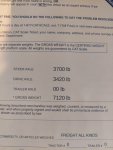
I estimated a curb weight of 3450/3100(6550lb total) but I just took it across a CAT scale today and it came in at 3700/3420(7120lb) curb weight with a full tank+me+100lb:
20241109_111910.jpg

So it might be a little heavy for the o'll armada springs, does anyone know what the real spring rate is for the 4x4 version??

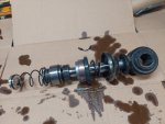
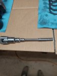
Also I found a better pick of the fully disassembled shock which shows the droop bump stop/inner tube hat that wasn't shown in the above pics:
20240904_135201.jpg

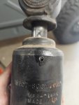
Lastly I found another pic that shows how far the upper shock hat slides into the outer shock tube body (How much below the crimped/swedged portion) :

20240904_134355.jpg
 

Attachments

Last edited:

Thunderbirds

Well-known member
262
377
63
Location
Northern Black Hills South Dakota
I have been riding around with this update for a bit now, about 200 miles/week. They are still working well and I am very happy with the value of the change. The ride on-road is much improved and makes the truck much more enjoyable to drive. Dirt roads and off road is again much better but I am still looking for an improvement.
Very impressive workmanship and ingenuity. Kudos!

Have you (for improvement) considered lowering your tire pressure? What are you currently running?

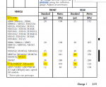
In my case, I found out (with the help of a few folks here on the forum) the curb weight plus driver and passenger calls for 15 and 18 PSI for my M1123, 10K setup. I couldn't stomach that low but with runflats I can see how that is possible.

Before, I had mistaken the max pressure as the required pressures @ 35 and 40 PSI... Those numbers are for GVW and driving on normal roads with minor potholes rattled the filling in my teeth. Every and any 1" rock or hole could be felt throughout the entire truck. I am also convinced many of my leaks and general looseness of items were caused by the constant and relentless hammering.

Now I run 21 and 23PSI, somehow I feel a better gas mileage at those pressures ( I know, better gas mileage with a HMMWV :LOL:). Unbelievable difference, I would compare it to a HD truck suspension but very much comparable to POV vehicles. And I haven't sacrificed any loading capability this way. If and when I have to load some weight, all I need to do is air up to specs. That change by itself has made a 99% improvement for me.

I also have noticed the stenciling on the fenders for the truck calling for 25 or up to 40 PSI is so misleading. This is for MAX PRESSURES at MAX WEIGHT LOADS, not empty driving. Everyone has their own opinion on what the right tire pressures are, however the TM is undeniable intended by the manufacturer.

Tire Pressure per TM.png
 

Thunderbirds

Well-known member
262
377
63
Location
Northern Black Hills South Dakota
Very impressive workmanship and ingenuity. Kudos!

Have you (for improvement) considered lowering your tire pressure? What are you currently running?

In my case, I found out (with the help of a few folks here on the forum) the curb weight plus driver and passenger calls for 15 and 18 PSI for my M1123, 10K setup. I couldn't stomach that low but with runflats I can see how that is possible.

Before, I had mistaken the max pressure as the required pressures @ 35 and 40 PSI... Those numbers are for GVW and driving on normal roads with minor potholes rattled the filling in my teeth. Every and any 1" rock or hole could be felt throughout the entire truck. I am also convinced many of my leaks and general looseness of items were caused by the constant and relentless hammering.

Now I run 21 and 23PSI, somehow I feel a better gas mileage at those pressures ( I know, better gas mileage with a HMMWV :LOL:). Unbelievable difference, I would compare it to a HD truck suspension but very much comparable to POV vehicles. And I haven't sacrificed any loading capability this way. If and when I have to load some weight, all I need to do is air up to specs. That change by itself has made a 99% improvement for me.

I also have noticed the stenciling on the fenders for the truck calling for 25 or up to 40 PSI is so misleading. This is for MAX PRESSURES at MAX WEIGHT LOADS, not empty driving. Everyone has their own opinion on what the right tire pressures are, however the TM is undeniable intended by the manufacturer.

View attachment 935398
.

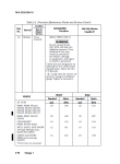
I need to add that the chart above is for Radial tires, here is the chart in the Operators Manual for BIAS tires. So use depending on your needs.


BIAS Tire Pressure per TM.png
 

mgFray

Well-known member
Steel Soldiers Supporter
712
982
93
Location
Southern Minnesota
That low of tire pressure absolutely destroys the sidewalls of the stock military tires.. I run my tires (after the first set experienced sidewall cracking) at 35 front/40 rear.. But I have an M998, not a completely different weight class... if I put a heavy load in it, I'll actually go DOWN in tire pressure a bit.

(I destroyed the first set at 20 front/30 in the back, since that was what my rig was marked at.. originally.)
 
Top
AdBlock Detected

We get it, advertisements are annoying!

Sure, ad-blocking software does a great job at blocking ads, but it also blocks useful features of our website like our supporting vendors. Their ads help keep Steel Soldiers going. Please consider disabling your ad blockers for the site. Thanks!

I've Disabled AdBlock
No Thanks