• Steel Soldiers now has a few new forums, read more about it at: New Munitions Forums!

  • Microsoft MSN, Live, Hotmail, Outlook email users may not be receiving emails. We are working to resolve this issue. Please add support@steelsoldiers.com to your trusted contacts.

Artisan's M916

Artisan

Well-known member
2,761
227
63
Location
CDA Idaho
Matt! I think your spacer is there and installed!

That means your Transfer Case Cooling pump is disengaged
and not pumping TC oil thru the cooler and being in Aridzona
you may want to remove the spacer. But do your
homework... ( But I think I am right)

Read the TM I think it says to remove the Spacer and install it so the
pump shaft engages, so you actually move the spacer to the very outside.


Its in the TM me thinks...
 

Artisan

Well-known member
2,761
227
63
Location
CDA Idaho
M916 a/c installation

A bunch of A/C units complete were sold recently
for the M915 A0 / A1 trucks. They WERE sold as #RD-2-4530-OP.
I have not read all the instructions word for word but I think
RD originally fit these for the M915 and assumed the
M916 M917 m918 M919 and M920 were all the same.

They are not.

If you look at the instructions all pictures seem to show
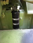
an M915, well, right away I ran into an issue w/ the Dryer.
It tells you to unbolt a 1/2" bolt and slap on the bracket
for the dryer, but if you have an M916 you will quickly see
that the M916 has an AIR TANK right where the dryer is supposed
to mount.

I think I found a work around, I hope I do not need
a elec harness extension but I believe it is available if needed.

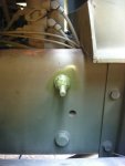
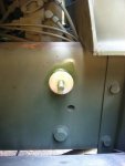
My workaround was to simply weld a 1/2" x 1.25" fine thread
bolt to the head of one of the large frame bolts. I would not
weld to the frame for many reasons so this seems to be a
good work around. Just weld on the bolt and put a thick
fender washer behind the dryer bracket and a washer on top
w/ a 1/2" fine thread oblong'd mil nut and call it good.
I hope it is good! I will find out when it comes time to
hose it and wire it I guess.

Here are some install instructions if you need them;

CLICK HERE
and
CLICK HERE

One file is kinda big.


PICTURES OF HOW I DID MY DRYER INSTALL ON MY M916
dryer4.jpg dryer3.jpg dryer2.jpg

More A/C install info coming.
 
Last edited:

R Racing

Active member
2,767
16
38
Location
St. Leonard, MD
I have a Hwwmv system ( its all I could get at the time) It will freeze you out of the cab for sure !! I kinda wish it would regulate like a cars ac. cause your freezing when its on . and you melting when its off lol you can see where I mounted mine. also cooked my alternator in the first 15 min of use . had to upgrade to a 200 amp unit with a step down box to make everything happy.
 

Attachments

Artisan

Well-known member
2,761
227
63
Location
CDA Idaho
M916 A/C Electrical Challenges

__ I found a post that NDT and R Racing were a part of a few
years ago that has some good info about our electrical systems.
To quote NDT;

"OK, quick explation of the 915/916/920 electrical system: 4 batteries, 2 in parallel for 12V, the second 2 also in parallel for 12V, both battery banks in series for 24V. 24V is used for the starter motor, 12 volts for everything else. The alternator produces 12 volts at 100 amps to charge the first battery bank, and 24 volts at 10 amps to charge both battery banks. If you connect a 24 volt air conditioner that draws 20 amps, the draw would exceed the alternator's capacity and the second bank of batteries would be drained."

CLICK HERE for where I got that quote from.


Castle Bravo and Alan just left here, they were here picking up CB's new
A/C unit, same unit NDT and I just purchased as well. So the electrical power
needs must be addressed. We talked a bit and I showed them my
battery box w/ just two batteries and ammo cans and CB suggested a
possible workaround; (I may have left a part out???)

Add two more batteries wherever you like.
Use the added two batteries for JUST the A/C needs.
Separate the two electrical systems w/ a battery isolator.

So I wanted to try to learn a bit more about battery isolators and
I found a youtube that does that pretty well, I believe we can just
swap our A/C system for the Sound System they speak of.

https://www.youtube.com/watch?v=CGD8HAeg5UA

I am HORRIBLE w/ electricity. Will this work? Are these battery isolators
smart in so much it will switch between batteries and keep both
banks charged or are we still lacking AMPS FROM THE ALTERNATOR
and do we need to beef up the alternators?

Should the starter and the A/C be on one bank and other systems on the other bank?
I am really grasping at thin air here.

Another suggestion is to add two more batteries so I have 4 like OE, wire them like it came factory
and then connect the A/C wires as the instructions say and call it done w/ the method of
the madness being that is how they all were done in the military.
 

NDT

Well-known member
Steel Soldiers Supporter
10,458
6,530
113
Location
Camp Wood/LC, TX
Artisan, I have since been brought up to speed on the A/C install by reb87. The kit as supplied by Red Dot does not overload the puny transformer-rectifier 24v supply on the 14-20 ton vehicles. RD would have done quite a disservice to our servicepeople in the sandbox if this kit automatically smoked the alternator.
 

Castle Bravo

Hundredaire Socialite
Steel Soldiers Supporter
1,964
215
63
Location
Arizona
The separate batteries idea was Allan's.

If the A/C unit's current draw exceeds the alternator's 24v output, the batteries reserve capacity should take up the difference, until they run out. With 4 batteries, this could very well be many hours. This may never happen, I'm not sure.

I believe NDT is correct in that Red Dot would not have sold the government a product that would not work without modification that is not mentioned in the installation manual.
 

Artisan

Well-known member
2,761
227
63
Location
CDA Idaho
Thank you CB for clarifications.

As you know, I started installing the RD-2-4530-0P A/C unit in my
M916, I HAVE THE CAT 7155 Transmission so this may apply or may not to you.
If you have an Allison the Evap unit will probably install per plan.

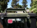
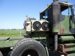
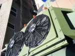
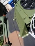
The condenser on the roof was pretty straight forward except I threw
away the silicone and used rubber washers between the roof and the
mount, then on top under a flanged head bolt, I used a SS backed
rubber sealing washer, all from McMaster. I first pulled the fans
and their control boxes and painted the condenser super-structure
383 green, then reinstalled the fans and bolted it down using my own
flange head hex bolts and nyloc nuts w/ a SS Fender washer underneath.
condensor-1.jpg condensor-2.jpg condensor-3.jpg condensor-4.jpg

I have a canvas type of cover being made as we speak that will cover
the fans in the off season or if bad conditions. Leaves and pine needles
will play helm w/ that unit if not kept clear. Plus you do not want
snow getting in there, and then a freeze come, it will blow things apart.

When you drill for the 4 rearmost bolts BE CAREFUL because the air horn
hose was right there. Speaking of air horn you have to remove the valve
to pull the headliner, good time to fix those leaks. After I bolted it down
I flooded my bolts w/ a pressurized hose, refit the headliner and all is well up top.

I went over the dryer already.

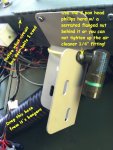
The evaporator WILL NOT FIT per plans. So what I did is I simply moved
the evap unit towards the PS door and used the next circuit box bolts.
No muss, no fuss.
Right-Side-AC-Bracketry.jpg
The drains, I added 2- 1.75" OD x 1" ID x THIN rubber
washers, super gluing them to the bottom of the evap unit around the drain
outlets so there is a seal. After all holes were drilled I painted the cuts as well.
The drain hoses they supply, well I ended up cutting one in half and using
two 1/2 as long pieces, you will see why. I have not installed them from
under the truck yet, it will be fun I am sure.
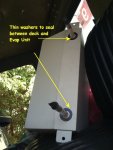
Deck-Drain-Holes.jpg
The M916 w/ CAT 7155 has an access panel on the floor directly under the ratio
selector box on the floor. BE SURE to remove the screws 1-2? that the Evap
unit will make impossible to remove in the future!

The part where you are suppose to cram the #6 Hose and the JUMPER wire assembly
and the power feed assembly through one of those cone shaped grommets is
a cruel joke. I got the Jumper and #6 hose through and decided to simply
pop a new hole in line w/ the two conical grommet holes and called it
better than good. Now the power lines are not SQUEEZED so tight. Just
grab a 3/4" x 3/8" rubber grommet good for and 1/8" thick deck and drill
a .55" hole, then cut the grommet so you can spread it around the convoluted
tubing and install it. The eye connectors for the battery need to be squeezed
gently to a smaller diameter to go thru the .55" hole.
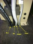
Right-Side-Deck-Holes.jpg
 

Artisan

Well-known member
2,761
227
63
Location
CDA Idaho
Fitting the EVAP and laying out all your holes is difficult if you have the 7155 tranny
since the template moves. I just cut out the center of the template and thru the
outside of the template away. After a lot of cussing, placing the evap unit on the floor
and marking the drain holes and bolt down holes pulling the unit in and out twice I
achieved perfection. GET A HELPER if possible. I did almost this whole job alone,
I had to get help to tighten condenser mount bolts and look for leaks.

Mounting the EVAP unit was difficult. I am not done either, you see we moved
the EVAP unit about 3" to the right so now the EVAP bracket that holds the
Switch box, now it is about 3" to far away! I have a fix for this, stay tuned.
 
Last edited:

Artisan

Well-known member
2,761
227
63
Location
CDA Idaho
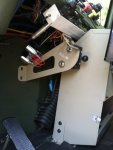
We moved the Evap unit to the right so now the bracket that holds
the Switchbox is askew. I simply grabbed a 3" x 3" x 3.75" x .125" thick
piece of square tube and massaged it smooth. Drill your mounting bracket
holes THRU 2 walls. I choose to add a RAM Mount ball for future goodies
as well.

NOTE: All of the female metric holes on the left and right side of my Evap
unit had to be chased w/ a metric tap, I think it is an M8-1.25.

I used the supplied bolts to mount my spacer to the Evap unit and then
my own bolts to mount the left side switch box holding bracket to the
spacer. Came out kinda like it grew there.

switch-bracket-2.jpg switch-bracket-1.jpg

I think I am very close to where the OE instructions say it would have
been, I hope so! HA! next to pop a couple of tiny holes thru into the
engine compartment and bolt this baby down so I can move on.

Every little part of this job IS A REAL JOB! I would charge HUGE money to do this
for someone else. (and do it to my liking anywho)

PS, that is a 12V 2 Switch, Lighted Rocker, Accessory Outlet for GPS etc hanging that
I need to strap up, soon, real soon. Right now it is almost 100 Degrees outside I bet,
tools are so hot you can not hold them.
 

NDT

Well-known member
Steel Soldiers Supporter
10,458
6,530
113
Location
Camp Wood/LC, TX
Lookin' good so far. Thanks for the write up. Couple questions. Do you like the look of the condenser up on top? Does it look out of place, or does it seem to be OK? Next, do you think the evap could go against the back wall of the cab? I think it would be less obtrusive there.
 

Artisan

Well-known member
2,761
227
63
Location
CDA Idaho
NDT,

I was concerned about the condenser look, that is why I went through changes
to paint it green. I am OK w/ the look, I almost like it. I am not done
up there too, I might spring for a bar type LED light or?. If it was the OE
color it would look horrid IMO.

I considered the Evap back there but I also realized that in the event
of a roll over it will make it that much hard to bail out. If necessary I
know I could bust that rear window out w/ my bare hands and bail. It
might freeze your head too . It is pretty heavy, you would need to build
a substantial shelf, any and all drilling and attaching to that back wall
will be kinda tricky to do it SOLID.

You could easily extend the drains if back there, if you needed a longer
piece of #12 hose you could get it easy, you could extend the power
harness easy, I think everything else will reach / work. You will need to fab up
bracketry on both sides at the top. I want cool air blowing
in my face to cool me off, not the side of my head or hoping the overall
temp I the whole cab will drop. THAT was the biggest deal for me.

W/ the 7155 one duct is kinda blocked by the ratio selector but I think
I can make a raised plenum for that if necessary but it might work
better w/ that far left duct pointing down, cooling the leg / feet area,
where a lot of engine/tranny heat comes from.

All in all the center floor of these trucks is unusable as it is. I was concerned
about the Evap being in the way for dash repairs but it could be pulled if
necessary. I am glad I kept it down there. Even though I shifted it to
the right 3" it still looks store bought and I will have cool air in my face.
 

Artisan

Well-known member
2,761
227
63
Location
CDA Idaho
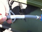
This kit is goofy, there are TWO SETS of drier plugs!

Look at your condenser, look at the condensors attached harness, you see those two, 2-pin plugs?

OK now look at your other harness'es, there is a harness that plugs into
this condenser harness and goes DOWN to the Drier and there is ANOTHER
set of drier plugs!

I "assume" we can just cut off these upper extra set of plugs.

This first picture is just a pic of the number on the CONDEENSOR HARNESS

extra-drier-connections.jpg

The pic is too big so CLICK HERE to see what I propose.
 

Artisan

Well-known member
2,761
227
63
Location
CDA Idaho
My next challenge is the wiring from the Evap to the Drier.

In the kit there is a JUMPER that you are supposed to connector to
the Evap unit and it goes down thru the floor and over to the drier.

Well, the harness that attaches to the drier has maybe a 16" long
pigtail that heads toward the Evap unit and the JUMPER harness
that comes from the Evap unit is only 4' long, NOW TRY TO CONNECT
the two centered almost on top of the 7155 tranny! LOL.


I found a workaround.

A guy "might" be able to get them connected but your close to the
tranny heater and things are going to be real tight so I have an extension
coming and all will be well again I thunk, so long as the double drier connection
deal works out!

aua
 

Artisan

Well-known member
2,761
227
63
Location
CDA Idaho
PS, when you go to drive home the #12 Freon connectors do
yourselves a HUGE FAVOR. Heat them up GOOD w/ a heat gun
first. trust me on this.

The #6 I had no problem w/ and I have not done a #8 yet but
I think I will just heat it up to be safe.

They are INSANELY hard to push together.
 

FASTNOVA

Well-known member
Steel Soldiers Supporter
1,093
146
63
Location
Los Angeles,Ca
That looks like a lot of work. How about you line the cab with a few of these and call it a day.

or worst case scenario you run out of batteries use one of these.
 
Top