• Steel Soldiers now has a few new forums, read more about it at: New Munitions Forums!

  • Microsoft MSN, Live, Hotmail, Outlook email users may not be receiving emails. We are working to resolve this issue. Please add support@steelsoldiers.com to your trusted contacts.

changing compression ratio on 602

jollygreen6x6

New member
54
0
0
What exactly would be the procedure needed to have the compression ratio on the 602 brought up to, say, 8-8.5 to 1? What valve modifications would be necessary? What could be the predictable performance gains? How likely is it that I would be capable of destroying a perfectly good engine by making the slightest mistake on valve adjustment? When I take it to a machine shop, what to I need to tell the machinist, and in what state do I haul in the heads(as in do I leave the valves in or not)?
I know this is alot of questions, but there is alot of information floating around here, and I'm sure someone can tell me something...

I really hate to tear apart and experiment upon a perfectly good 602, since all I had to do with it when I got it was clean the carb, new plugs and wires, timing, and change the oil. After that, purred like a 6000 kitten... :roll:
 
Hey Chuckles,
I’ll give it a shot, since I might be partly responsible for bringing up the subject in another thread you started:
“turbo 602?” http://www.steelsoldiers.com/DotNetForum/default.aspx?f=68&m=16571
Elwenil jumped in with some good points to consider there as well.

Here is a site that has some basic information: http://www.carcraft.com/techarticles/982/

I'm working on writing something up, but I keep getting interupted.

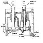
In the meantime, Shown below is a diagram that I copied from:

TM 9-2805-203-35 January 1965
FIELD AND DEPOT MAINTENANCE MANUALFOR ENGINE, ASSEMBLY W/ACCESSORIES (CONTINENTAL MODEL R-6602) AND CLUTCH (ROCKFORD MODEL 15TM)

This shows a cross-section of the cylinder head. I am ASSUMING that this diagram is to scale and accurately depicts the actual 6602 head. more to follow.
 
Ok, I found some more time to work on this, so here is part #2

Let me first make this disclaimer: I am not an expert in this subject. :confused:I only know enough to be dangerous. I am just trying to provoke(invoke?) some further discussion on this topic. All of the assumptions I am presenting should be thoroughly researched.
Secondly, I [red]DO NOT [/red] advocate trying this on a perfectly good running engine!
What we really need is a sacrificial engine on which to conduct some experiments. Does anyone have a junk head we can use for practice?


What we have to do is see if we can figure out the volume of the combustion chamber with the piston all the way down, and then again with it all the way up. Those two numbers establish the compression ratio. Then we need to try to figure out if it is possible to mill the head to change the compression ratio to something more desirable.
As stated in the Car Craft article (above post): There are five factors that affect compression ratio: cylinder swept volume, clearance volume, piston dome or dish, head-gasket volume, and chamber volume.

[red] 1) Cylinder Swept Volume[/red]
We can easily find the first part - Cylinder Swept Volume (The swept volume of the cylinder indicates how much air the piston displaces as it moves from BDC to TDC.) From the tm:
Bore . . . . . . . . . . . . . . . . . . . . . 4-7/8 in.
Stroke . . . . . . . . . . . . . . . . . . . . 5-3/8 in.

From high school geometry (remember that?)
volume of a cylinder = (pi) (radius [sup]2[/sup]) x height = 100.3 cu in (that is the volume of the piston’s stroke of one cylinder. )
(. . . or we could have taken 602 cu in divided by 6 (# of cylinders) = 100)

[red]2)Clearance Volume[/red]
For this, we need to know the deck height. In other words, when the piston is a TDC, how close is it to the top of the block? There is probably a gap between the top of the piston and the top surface of the block. I don't know what this number is. Can' t find it in the TM. We will have to measure it somehow. Again, anyone have a donor motor for sale? (another topic for discussion at a later time is - can this deck height be machined instead of the head? maybe, but more work)


[red]3) Piston dome or dish[/red]
I don't know this one either. I would assume flat-tops, but???


[red]4)Head Gasket Volume[/red]
The calculation here is the same as 1), but the height is the thickness of the head gasket. Need to measure gasket thickness.


[red]5)Chamber Volume[/red]
Only way I know how to get this one is to cc the head. This involves laying the cylinder head upside down on the workbench. Then fabricate a cover plate (preferably transparent plexiglass or polycarbonate). Then with a graduated measuring device, add water (or suitable liquid) to fill the chamber.


Ok. so if we take some measurements as describe above, and do some math, we can determine if it is theoretically possible.


Let' s assume it is and jump ahead.
Let’s look at the clearance between valves and top of the piston. (we want to avoid collision - would be disastrous!)

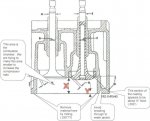
Shown below is a diagram that I copied from:
TM 9-2805-203-35 January 1965
FIELD AND DEPOT MAINTENANCE MANUALFOR ENGINE, ASSEMBLY W/ACCESSORIES (CONTINENTAL MODEL R-6602) AND CLUTCH (ROCKFORD MODEL 15TM)

This shows a cross-section of the cylinder head. I am ASSUMING that this diagram is to scale and accurately depicts the actual 6602 head. This is just an assumption! It is possible that the manual is using a generic picture. We will need to verify the assumptions based on this picture!!

1) The manual lists the inside diameter of the intake valve stem guide as .4985- .4990 (shown by letter B above) . . . for argument’s sake that is close enough to ½”, right?

2) The manual lists the following information for the valve springs:
Spring height at 1.367 - inch length
(valve open)
Spring height at 1.867 - inch length
(valve closed)

If we subtract the length of the spring from open to close – it is exactly .500 (or ½ inch) Theoretically then, the valve is opening into the chamber ½”.

The available area for the valves to travel in the combustion chamber is shown by the dimension with the red “x”. By rough scaling, it appears that “x” is a little more than 1”. From the above statement, we know that the valve only travels ½”, therefore, there should be ½” clearance left between the valve and the bottom of the cylinder head where it mounts to the top of the engine block (also known as the deck).

So how much material can we remove by milling? I have this shown as red “Y” in the diagram. I would caution here that the most I would consider would be about half of the thickness available or about .250”, again based on rough scaling of the diagram. That would leave enough of the casting (about .250”) to avoid breaking thorough to the water jacket.


Ok, that's all for now. more to follow.[red] [/red] [sub][/sub]
 

jollygreen6x6

New member
54
0
0
This is starting to sound like an idea. I may look into purchasing another set of heads, and at sometime having them milled, so that if/when headgasket time comes around, put them on and see what happenes...
 

JasonS

Well-known member
1,650
144
63
Location
Eastern SD
I would recommend improving the ignition. My understanding is that the reo and the continental have similar distributors but turn opposite directions? You can easily modify a non computerized mini HEI distributor from a 2.8L chevy V6 to work in the reo. The potential issue with the continental is that the centrifugal advance won't work. I am also examining the pertronix ignition module for the original waterproof distributor. If you go that route, you would need to use the 3ohm coil and a solid state voltage reducer to drop the 24 down to 12V.
 
JasonS said:
If you go that route, you would need to use the 3ohm coil and a solid state voltage reducer to drop the 24 down to 12V.
Hey Jason (or anyone else who is sharp on this electrical stuff),

Could you elaborate about adapting a 12V coil? I think my coil is going south, and I was wondering about swaping in a 12v one.
  • *Can you describe the Parts you are refering to above? Are there part numbers?
  • *Where do you get them - NAPA, Grainger, Radio Shack?
  • *How are the parts wired together?
  • *Do I need a schematic?

Thanks,
Jeff
 

JasonS

Well-known member
1,650
144
63
Location
Eastern SD
My REOs have standard size and shape Delco coils with a 1.5ohm primary resistance. As far as I can tell, there is nothing special about a "24V" coil. The only thing that you have to be concerned with is the primary resistance (+ to - side) which determines the maximum current through the points. NAPA should have something. Take along your meter and try to get a coil with near 1.5 ohms primary resistance and NO internal ballast resistor. Unscrew the plug in the end of your original coil spark tower and swap it with the terminal in your new coil. I test fit a chrome ACCEL coil (1.2 ohms) and all it would have required was some trimming of its taller spark tower. I have found NO advantage to the "higher output" coils when using points ignition.


I haven't done the Pertronix conversion yet but it appears that you could use the 1167 module, 3 ohm coil, and a linear regulator to drop the 24V down to 12V. The selection of linear regulator would depend on the current draw. The plan would be to remove the existing ballast resistor and install an aluminum slug to which I could bolt the regulator (for a heatsink).
 

jollygreen6x6

New member
54
0
0
Well, oddly enough, my M-54 was "converted" to 12 volts. When I say "converted", I mean a 12 volt distributor from who-knows-where, and all the other stuff is still origional. Starts, runs, and charges off of 12. though. I keep seeing these points-eliminator things, and have been thinking of applying one with a high power coil. I still want to look into milling cylinder heads to make my gas money worth it.
 
Hey JasonS,

Could you please look at this and give me your opinion??

I went to the Summit Racing website ( if you are not familar, they are a mail-order hot rod supplier) They have a great search feature. They list four coils that have the 1.5 ohm primary resistance that you recommend, but what about the other parameters listed (i.e. inductance, secondary resistance, etc.)?

Didn't see any mention of the NO internal ballast resistor. Prices are all about the same, so no issue there. Which do you think is best?

http://store.summitracing.com/defau...archinresults=false&N=0&target=egnsearch.asp

Thanks, Jeff
 

JasonS

Well-known member
1,650
144
63
Location
Eastern SD
Jeff,
I haven't compared many igntion coils but I'll relate what I do know. I have tested an Accel super coil, Accel round chrome coil, stock coils, and HEI E-core coils. I haven't found a noticeable difference between the accels and stock coils when using points. This is the limitations of points ability to break the field quickly and put all of the energy into the secondary. The HEI and Accel super coil/Mallory unilite were the best. The chrome accel coil/mallor unilite was a slightly weaker. I don't have any quantitative data, just the relative maximum spark length. The stock 24 volt system isn't bad, though. Fires a 0.035 plug gap OK. This is enough for the low compression, low speed truck engines. I run a mallory unilite on my 302 gmc (hot cam, 4bbl, headers). Not much improvement until I opened up the plug gap to .050" at which the idle smoothed out considerably.

I haven't delved deep enough to measure inductance or secondary resistance. I suspect that there is little real difference between aftermarket coils (at least for the normal round variety). The higher performance coils may have lower inductance to allow for quicker saturation but this is of less imortance for a low speed 6 cylinder which has more dwell time. The accel chrome coil (8140C) fits the Reo disty with a little grinding of the tower. I didn't see any improvement compared to the stock coil so it went on another application. I would recommend finding something that fits physically and is near 1.5ohms. If you want better, you want electronic ignition. I would also recommend ditching the shielded wires so that you can normal (inexpensive) plugs.

Hope this helps...
 

big daddy

New member
62
1
0
The 12 volt 602 distributor you have like mine comes from heavy equipment, my M54 had a rebuilt 602 from a grader installed along with all the related 12 volt equipment. The problem with raising the compression may come up in getting a stronger starter and depending on how high you go ,better fuel ( these things are thirsty enough without having to buy a higher grade gas ). One other thought I read somewhere that increasing compression ratio 1 full point eg. 6 to1 - 7 to 1 will only increase power a small % , one would think the better way to do this would be to get a better trans ( more gears + overdrive ) or do both ?
 

73m819

Rock = older than dirt , GA. MAFIA , Dirty
Steel Soldiers Supporter
In Memorial
12,195
325
0
Location
gainesville, ga.
Bring this thread back to life, since we have a PARTS 6602, which means a EXTRA set of heads and since the RESTORED restored m62s number 5 hole is sucking oil though the intake valve guide which means a head job, so this means we can/are going to put some of above theory into practice. Going to start by shaving the extra heads 3/16", this ought to help to bring the compression up to take advantage of the modern, higher octane gas, really can not take more for a few reasons, The first is valve lash adjustment because there is only a touch over 1/4" that can be had still using OM push rods, The second is the "head deck" on the spark plug side is only 5/8" thick (head bolt hole boss is 3/4"), even though the head IS CHROME MOLLY, we do WANT to take the chance when hot of starting a crack in the deck, if one starts it would be almost impossable to stop or fix, so that would mean ANOTHER head job, with about 500lbs of stuff to pull (not counting the heads) to pull the heads, we want this to be a ONE time change.

After the heads along with some updated timing, we are going to do holly carb TWEAKING including installing a o2 sensor, then ignition TWEAKING, maybe even installing electronic ignition. The plan is to do ONE thing at a time, working from the existing baseline, start doing a bunch at one time will ONLY turn into a cluster -.

Anybody have any ideas on this project, remember the ideas must be cost efficient, this means no turbo or no custom manifolds, ect., these kind if ideas will never break even the cost even if the m62 is used 40 hours a week.

One more thing, ANYBODY know a OLD, I mean OLD time truck mechanic that worked on these BIG OLD CIVI GASSERS (like the 6602, the White 390a( 531 cid 6) the Autocar 805 (805 cid 6) ect.) when they were used in everyday over the road use, because I would like to talk to him about the tricks that was used back then, these cannot be found in any books..
,
 

ReoRider

Member
165
11
18
Location
Vermont
Ah, Continental 6602 one of my favorite gas engines (next to the Reo Gold Comet). Have had a chance to try out some of your ideas on two 602 installs in an M52 tractor.
Removed .125 (1/8") off of the heads, where the only additional fitting needed was on the water plumbing connections to remove interference. Quite noticeable performance increase, no downside observed. Agree, could possible go further, but this worked without any concern about the other issues you raised.

Always had problems with the Holly running rich, not just at idle, so installed the later issue kit (think is a Rochester-can check) that the military used to keep the M62 wreckers running, with the original gas engines, when the Holly supply ran out. MUCH better match to the engine; no restart flooding, and the trucks following you don't get gassed with the unburned fumes.


Ignition was improved with considerable advance in the timing (adjust to taste) and good point /plug maintenance. Have not played with solid state unit as I always felt the relatively low revs (compared to modern engines) and the always good hot spark from the 24 volt coil was enough. Would be interested in any experience with a replacement unit.

Other related change was the use of the Overdrive version of the Spicer. Given that the 602 will rev relatively high for a big motor(look at the specs for White and Hercules at the time), but you don't always need max HP as often as you do low end torque. This allows you to loaf along in 5th quite often at a good torque point and still have the higher top speed available. The little loss of gear ratio at starting (when heavy) is handled by low range starts(L2 to L3) then up through the high range gears. Easy shifting with the syncro transfer case.

This set-up has been in use for over 15 years, hauling 64,000 gross (M52, semitrailer, Stuart tank) to shows and meets in four states. Lots of time spent shifting in the hill country here, but great fun!

John
 

steelypip

Active member
769
68
28
Location
Charlottesville, VA
Given that it's a slow engine, the logical ignition upgrade would not necessarily be a hotter coil (higher voltage spark), but either multiple spark plugs per chamber (very hard to do), or an MSD box (very easy to do). You don't really get any value out of a hotter coil (presuming the old one was in good order) unless you open up the spark plug gap some, which puts more stress on all the other ignition system components.

The MSD box gives the plug multiple chances to ignite the charge on every stroke, which equals more power due to less misfire and more even loading between the cylinders. I have had good success in going to electronic ignition on an engine like this - the transistor has a faster cutoff than points, which equals a shorter rise time for the spark and a higher peak voltage from the same coil.

Raising the compression, putting on an MSD box on, and a decent carburetor would be excellent first steps. Probably the next step would be to do something about that intake manifold. There's probably 20 HP and some fuel economy in getting something that flows decently to the outer cylinders. The easy way would be to port it; the right way would be to weld something up, probably dual plane with alternate phasing. When you get to the tuning stage, you'll want to do a loaded pull up a hill and shut off at the top and check the plug coloring. I would be surprised if the mixture distribution was very good.
 

patracy

Administrator
Staff member
Administrator
14,639
4,818
113
Location
Buchanan, GA
Seems to me that one could source some custom pushrods or a different appliation's pushrod to help get the valve adjustment back into a factory realm.
 

73m819

Rock = older than dirt , GA. MAFIA , Dirty
Steel Soldiers Supporter
In Memorial
12,195
325
0
Location
gainesville, ga.
Seems to me that one could source some custom pushrods or a different appliation's pushrod to help get the valve adjustment back into a factory realm.
I can get factory valve adjustment with a 3/16" shave, being I can back up the adjustment a tad over 1/4", as I said in me thread revive post we are staying AWAY from custom work, the cost far out weighs the benefit.

One more thing, we are going to use civi specs, for setting the heads up and the timing.

We are not looking for more speed, just better performance, The problem with the od trans is the HOLE between 3rd and 4th, being the assigned mission of the m62 is not as a road truck (like a tractor) but mostly low range duty, the current or its twin trans is the trans of choice.
 
Last edited:

73m819

Rock = older than dirt , GA. MAFIA , Dirty
Steel Soldiers Supporter
In Memorial
12,195
325
0
Location
gainesville, ga.
Ha, almost 9 years later. . . . .

I noticed that the diagram that I referenced in the third post is gone. Probably from one of the many server crash/upgrade iterations since 2005.
Anyway, from the Crusher archives, here it is :

View attachment 491290View attachment 491289
After having the heads in my hands, I would NOT try a 1/4" cut, just to close to water jacket and the deck area by the plugs, think a cut of this size "could" cause a crack to start, there is a REASON for the massive amount of metal that makes up the head. 3/16" is about as much of a cut that I would dare try and be fairly comfortable with.
 
Top