Ok, I found some more time to work on this, so here is part #2
Let me first make this disclaimer: I am not an expert in this subject.

I only know enough to be dangerous. I am just trying to provoke(invoke?) some further discussion on this topic. All of the assumptions I am presenting should be thoroughly researched.
Secondly, I [red]
DO NOT [/red] advocate trying this on a perfectly good running engine!
What we really need is a sacrificial engine on which to conduct some experiments. Does anyone have a junk head we can use for practice?
What we have to do is see if we can figure out the volume of the combustion chamber with the piston all the way down, and then again with it all the way up. Those two numbers establish the compression ratio. Then we need to try to figure out if it is possible to mill the head to change the compression ratio to something more desirable.
As stated in the Car Craft article (above post): There are five factors that affect compression ratio: cylinder swept volume, clearance volume, piston dome or dish, head-gasket volume, and chamber volume.
[red] 1) Cylinder Swept Volume[/red]
We can easily find the first part - Cylinder Swept Volume (The swept volume of the cylinder indicates how much air the piston displaces as it moves from BDC to TDC.) From the tm:
Bore . . . . . . . . . . . . . . . . . . . . . 4-7/8 in.
Stroke . . . . . . . . . . . . . . . . . . . . 5-3/8 in.
From high school geometry (remember that?)
volume of a cylinder = (pi) (radius [sup]2[/sup]) x height = 100.3 cu in (that is the volume of the piston’s stroke of one cylinder. )
(. . . or we could have taken 602 cu in divided by 6 (# of cylinders) = 100)
[red]2)Clearance Volume[/red]
For this, we need to know the deck height. In other words, when the piston is a TDC, how close is it to the top of the block? There is probably a gap between the top of the piston and the top surface of the block. I don't know what this number is. Can' t find it in the TM. We will have to measure it somehow. Again, anyone have a donor motor for sale? (another topic for discussion at a later time is - can this deck height be machined instead of the head? maybe, but more work)
[red]3) Piston dome or dish[/red]
I don't know this one either. I would assume flat-tops, but???
[red]4)Head Gasket Volume[/red]
The calculation here is the same as 1), but the height is the thickness of the head gasket. Need to measure gasket thickness.
[red]5)Chamber Volume[/red]
Only way I know how to get this one is to cc the head. This involves laying the cylinder head upside down on the workbench. Then fabricate a cover plate (preferably transparent plexiglass or polycarbonate). Then with a graduated measuring device, add water (or suitable liquid) to fill the chamber.
Ok. so if we take some measurements as describe above, and do some math, we can determine if it is theoretically possible.
Let' s assume it is and jump ahead.
Let’s look at the clearance between valves and top of the piston. (we want to avoid collision - would be disastrous!)
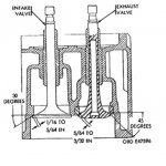
Shown below is a diagram that I copied from:
TM 9-2805-203-35 January 1965
FIELD AND DEPOT MAINTENANCE MANUALFOR ENGINE, ASSEMBLY W/ACCESSORIES (CONTINENTAL MODEL R-6602) AND CLUTCH (ROCKFORD MODEL 15TM)
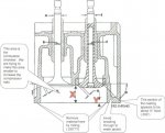
This shows a cross-section of the cylinder head. I am ASSUMING that this diagram is to scale and accurately depicts the actual 6602 head. This is just an assumption! It is possible that the manual is using a generic picture. We will need to verify the assumptions based on this picture!!
1) The manual lists the inside diameter of the intake valve stem guide as .4985- .4990 (shown by letter B above) . . . for argument’s sake that is close enough to ½”, right?
2) The manual lists the following information for the valve springs:
Spring height at 1.367 - inch length
(valve open)
Spring height at 1.867 - inch length
(valve closed)
If we subtract the length of the spring from open to close – it is exactly .500 (or ½ inch) Theoretically then, the valve is opening into the chamber ½”.
The available area for the valves to travel in the combustion chamber is shown by the dimension with the red “x”. By rough scaling, it appears that “x” is a little more than 1”. From the above statement, we know that the valve only travels ½”, therefore, there should be ½” clearance left between the valve and the bottom of the cylinder head where it mounts to the top of the engine block (also known as the deck).
So how much material can we remove by milling? I have this shown as red “Y” in the diagram. I would caution here that the most I would consider would be about half of the thickness available or about .250”, again based on rough scaling of the diagram. That would leave enough of the casting (about .250”) to avoid breaking thorough to the water jacket.
Ok, that's all for now. more to follow.[red] [/red] [sub][/sub]


