• Steel Soldiers now has a few new forums, read more about it at: New Munitions Forums!

  • Microsoft MSN, Live, Hotmail, Outlook email users may not be receiving emails. We are working to resolve this issue. Please add support@steelsoldiers.com to your trusted contacts.

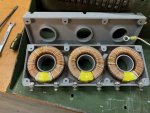
current sensor - mep803/2

zarathustra

Active member
Steel Soldiers Supporter
235
60
28
Location
glasgow,ky
Ok all you gen techs out there. Ever have trouble with a current sensor? If so, what were the symptoms of a bad current sensor?

I can't imagine what could go wrong with one of them, but I'd just like to know how a bad current sensor manifests itself.

It has no moving parts, and is 100% passive, so I have a hard time imagining one going bad.....
 

kloppk

Well-known member
Steel Soldiers Supporter
2,168
3,610
113
Location
Pepperell, Massachusetts
I'd imagine it would fail when one of it's windings develops and open circuit. That would cause the %Load meter to cease working for that specific phase.
No moving parts but it could be due to a latent manufacturing defect. Also heat stress or breakdown it's housing to causing it to distort or crack causing a break in one of it's windings.
 

Ray70

Well-known member
Steel Soldiers Supporter
2,632
6,057
113
Location
West greenwich/RI
I've never seen a bad one on an 802/803 but I have seen several on the older 002/003. Just like kurt said, either an open or any out of spec resistance reading on a single winding will cause issues. On the 002/003 it can cause no power output from the machine or incorrect / erratic power readings
 

Dieselmeister

Well-known member
Steel Soldiers Supporter
198
276
63
Location
Flagstaff, Az
A current sensor is basically a current transformer that transforms current to current at a specific ratio. I don't know what the ratio on the generator CT is, but the industry standars is current input / 5 amps output. so a 100/5 transformer would give you 5 amps out when the wire through the dougnut hole has 100 amps on it. Most industrial current meteres are all 5 amps full scale, and then they just print the actual amps on the face of the meter. Like previous members stated, if the winding goes open, you will get no output. If some of the windings short internally, you would get a different ratio, and the output would read different.

One danger with CT's is, that it will try to push out whatever the current the input and ratio are telling it to. If you open the output lead on an active CT, the voltage will try to go to infinity, since it is trying to maintain the current flow in a now open circuit. If you are holding one of those leads, that can really light up your life or shorten it! This can also cause arcing, and possibly arc and burn out the CT internally. It is similar to a Tesla coil - very few windings on the primary, and lots of windings on the secondary.

A quick test would be to check the resistance of all three windings with a precision ohm meter. They shoulds all be the same. Injecting and measuring a known current is another way to test CT's, but that's too much to describe here for now.
 

zarathustra

Active member
Steel Soldiers Supporter
235
60
28
Location
glasgow,ky
Well.... I had thought the current sensor might be bad, but I couldn't imagine what could go wrong with it. I was hoping that someone might have had some experience with a bad one and some failure modes for them. I intensely dislike "shotgunning" a problem... when I replace a part I always want to know why I'm doing it and what evidence I have that the part is, in fact, bad.

I had measured continuity of CT1, CT2, & CT3 a week or so ago and all was just hunky dory.

WELL...... Just as a lark, today I compared those readings with a known good sensor that was sitting on the shelf, and the "light popped on"!

The dodgy current sensor CT's all had continuity, but they also had continuity with each other!
So, no wonder that the overload circuit got confused when the 803a was drawing only 16 amps.

So.... if one has a problem with a phantom overload, check the CT's to make sure that each CT talks to itself and not to any other CT. The only way to check this out for absolutely sure is to disconnect one wire from each CT and measure.

Once I get this thing removed I'm going to take it apart..... I really want to see what a totally fried CT looks like. From the outside it looks just fine.

When I was in the Navy I was a CT..... there were a few of 'em that were totally fried as well.......
 

Dieselmeister

Well-known member
Steel Soldiers Supporter
198
276
63
Location
Flagstaff, Az
[QUOTE="zarathustra, post: 2328621, member: 54795"
The dodgy current sensor CT's all had continuity, but they also had continuity with each other!
[/QUOTE]

Make sure you disconnect both wires of the CT when testing. They are all three connected to each other in the overcurrent relay, and will look like they have continuity with each other.
 
Top
AdBlock Detected

We get it, advertisements are annoying!

Sure, ad-blocking software does a great job at blocking ads, but it also blocks useful features of our website like our supporting vendors. Their ads help keep Steel Soldiers going. Please consider disabling your ad blockers for the site. Thanks!

I've Disabled AdBlock
No Thanks