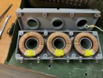
A current sensor is basically a current transformer that transforms current to current at a specific ratio. I don't know what the ratio on the generator CT is, but the industry standars is current input / 5 amps output. so a 100/5 transformer would give you 5 amps out when the wire through the dougnut hole has 100 amps on it. Most industrial current meteres are all 5 amps full scale, and then they just print the actual amps on the face of the meter. Like previous members stated, if the winding goes open, you will get no output. If some of the windings short internally, you would get a different ratio, and the output would read different.
One danger with CT's is, that it will try to push out whatever the current the input and ratio are telling it to. If you open the output lead on an active CT, the voltage will try to go to infinity, since it is trying to maintain the current flow in a now open circuit. If you are holding one of those leads, that can really light up your life or shorten it! This can also cause arcing, and possibly arc and burn out the CT internally. It is similar to a Tesla coil - very few windings on the primary, and lots of windings on the secondary.
A quick test would be to check the resistance of all three windings with a precision ohm meter. They shoulds all be the same. Injecting and measuring a known current is another way to test CT's, but that's too much to describe here for now.


