• Steel Soldiers now has a few new forums, read more about it at: New Munitions Forums!

  • Microsoft MSN, Live, Hotmail, Outlook email users may not be receiving emails. We are working to resolve this issue. Please add support@steelsoldiers.com to your trusted contacts.

Diagnostic Readers

Third From Texas

Well-known member
2,766
6,498
113
Location
Corpus Christi Texas
After so many wrong cables (to include the J1708 Deerborn originally sent me) and the ones I got off Amazon that were wired VERY wrong for a DPA and the one that came with my DPA4 that is also wire differently) I just wanted to be absolutely certain before I plugged something into the truck.

Yeah, as soon as I saw the truck talking to the Deerborn diag software, I knew I was on the downhill leg. I read thru most of the CAT ET user manuals last night and I at least have a pretty good grasp of what not to screw with. LOL

Thanks again!

Now to test the other DPA4 I acquired....
 

Lostchain

Well-known member
Steel Soldiers Supporter
285
587
93
Location
Portland, OR
I read thru most of the CAT ET user manuals last night and I at least have a pretty good grasp of what not to screw with.
First thing you should do ASAP is pull an ECM replacement file. You absolutely need to have this on hand and backed up in places because it has truck specific information you need if your Cat ECM ever dies. Injector trim files, timing calibration, and FLS/FTS, are setting’s unique to your truck that are very difficult/impossible to recreate if you don’t have the backup
 

Third From Texas

Well-known member
2,766
6,498
113
Location
Corpus Christi Texas
First thing you should do ASAP is pull an ECM replacement file. You absolutely need to have this on hand and backed up in places because it has truck specific information you need if your Cat ECM ever dies. Injector trim files, timing calibration, and FLS/FTS, are setting’s unique to your truck that are very difficult/impossible to recreate if you don’t have the backup

Thanks. Will do.
 

Third From Texas

Well-known member
2,766
6,498
113
Location
Corpus Christi Texas
Looks like the second reader I picked up (DPA4, not a Plus) isn't talking.

It has power and I can see it POST as startup (all the lights work at start) but it's not passing a signal to the PC.

I'm using the known good DPA4+ cable. I have the DPA4 and DPA4+ drivers installed. And I tried all the DPA4 settings in the Deerborn Diag software.. Looks like it's just not happy.

The (hand made) cable that came with it had one data wire out of whack (pin 7 and 5 are swapped). I'm not using that cable. Everything I read tells me that's wrong and the cablers should be the same. In any event, with the known-good DPA4+ J1939 cable....and the known-good USB-to-PC connection it's not talking.

Looks like this one is going back to the seller.

unnamed.png
 

Third From Texas

Well-known member
2,766
6,498
113
Location
Corpus Christi Texas
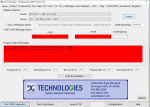
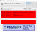
Big old wall of unhappy red.

I tried all the various combinations of Vendors, Adaptors, and Protocols.

All red and dead.

The only thing that flagged me was it says I have an .ini file that needs replacing. It did the same with the DPA4+ and I tld it to fix the file. It indicates that it did successfully, but even after a reboot I get the same flag. The DPA4+ works fine in any event.

The DPA4 looks to simply not be chatting.


unnamed.png
 

Lostchain

Well-known member
Steel Soldiers Supporter
285
587
93
Location
Portland, OR
Big old wall of unhappy red.

I tried all the various combinations of Vendors, Adaptors, and Protocols.

All red and dead.

The only thing that flagged me was it says I have an .ini file that needs replacing. It did the same with the DPA4+ and I tld it to fix the file. It indicates that it did successfully, but even after a reboot I get the same flag. The DPA4+ works fine in any event.

The DPA4 looks to simply not be chatting.


View attachment 909835
Yeah, seems busticated…. There is a firmware tool that comes with the Dearborn drivers that you might see if it detects the adapter, but that one might be a lost cause.
 

Third From Texas

Well-known member
2,766
6,498
113
Location
Corpus Christi Texas
First thing you should do ASAP is pull an ECM replacement file. You absolutely need to have this on hand and backed up in places because it has truck specific information you need if your Cat ECM ever dies. Injector trim files, timing calibration, and FLS/FTS, are setting’s unique to your truck that are very difficult/impossible to recreate if you don’t have the backup

I did get a backup made.

I tinkered with the Trainer before attempting anything just to be sure.

Interestingly, in the trainer it didn't get a snapshot of the injectors. And the same thing happened when I made the actual replacement file for the truck.
 

Lostchain

Well-known member
Steel Soldiers Supporter
285
587
93
Location
Portland, OR
I did get a backup made.

I tinkered with the Trainer before attempting anything just to be sure.

Interestingly, in the trainer it didn't get a snapshot of the injectors. And the same thing happened when I made the actual replacement file for the truck.
You are saying that creating the ECM Replacement file did not download the injector trim information? It’s been a while since I have looked at a C7 ECM replacement file, but if you open the file with an XML viewer like Chrome or Edge you will see the injector trim files encoded into the file.
 

Third From Texas

Well-known member
2,766
6,498
113
Location
Corpus Christi Texas
You are saying that creating the ECM Replacement file did not download the injector trim information? It’s been a while since I have looked at a C7 ECM replacement file, but if you open the file with an XML viewer like Chrome or Edge you will see the injector trim files encoded into the file.
Yeah, I got a popup stating:

"Cannot load Injector Trim Calibration from the ECM."

I'll have to doink around with it tomorrow. As I said, the Trainer also runs that same error msg (although I only played with one engine in the trainer).
 

hike

—realizing each day
Steel Soldiers Supporter
531
838
93
Location
Texas Hill Country
The Bluefire is up and talking to my tablet. I plugged in my J1939 Y splitter and landed one end for the OEM 24v diag port and the other end I clipped the 24v lead and fed it 12v.

Plugged in the Bluefire and all was happy. Had to register the adaptor, download some gauge packs, and off to the races. Typical learning curve stuff as with any new device. I will have to tweek a custom gauge layout to fit my $50 tablet and layout what gauges and colors I want to see, but overall it was quite painless. VERY pleased with this side of the project. VERY pleased....

The DPA4 is another story. The DPA4+ uses a 15 pin data connector. I found a 9-pin J1939 to 15-pin data cable. NONE of the wiring match up to the way the DPA4 is pined on the 15-pin side. So I'll either have to spend a few days on the electronic bench cussing and screaming at the wires.....or pay Deerborn the $500 they likely want for the $20 cable. LOL
What did you tap for 12v to run the Bluefire?
 

Third From Texas

Well-known member
2,766
6,498
113
Location
Corpus Christi Texas
That need will come up again - run a fuse panel off the 12v ignition relay under the PDP for accessories.
Yep.

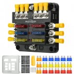
I tapped 12v at the PDC, ran a wire (in a plastic loom) thru the forward most body panel Then I added a 6-gang fuse block screwed onto the firewall on the driver side behind the kick panel. Handy for future additions, but the main goal was to fuse protect the Bluefire.


81ibJscCReL._SL1500_.jpg
 

ramdough

Well-known member
1,554
1,729
113
Location
Austin, Texas
Yep.

I tapped 12v at the PDC, ran a wire (in a plastic loom) thru the forward most body panel Then I added a 6-gang fuse block screwed onto the firewall on the driver side behind the kick panel. Handy for future additions, but the main goal was to fuse protect the Bluefire.


View attachment 910854
I bought the same fuse block. Or one very similar. Be sure to snug down the first double nut to the buss bar or the bolt will wobble and not be bonded well to the buss bar.


Sent from my iPhone using Tapatalk
 

hike

—realizing each day
Steel Soldiers Supporter
531
838
93
Location
Texas Hill Country
Yep.

I tapped 12v at the PDC, ran a wire (in a plastic loom) thru the forward most body panel Then I added a 6-gang fuse block screwed onto the firewall on the driver side behind the kick panel. Handy for future additions, but the main goal was to fuse protect the Bluefire.


View attachment 910854
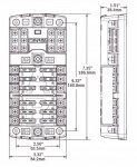
I like this split bar one:

IMG_3054.jpeg

After thinking I could adapt the unused PDP slots to new uses I realize your suggestions are cleaner and easier to document/isolate when gremlins appear. Now I am pondering either one split by 12v/24v battery or two 12v/24v each split battery/ignition. Forcing me to plan out all we wish to have runninng only with ignition on—
 

Third From Texas

Well-known member
2,766
6,498
113
Location
Corpus Christi Texas
I like this split bar one:

View attachment 910900

After thinking I could adapt the unused PDP slots to new uses I realize your suggestions are cleaner and easier to document/isolate when gremlins appear. Now I am pondering either one split by 12v/24v battery or two 12v/24v each split battery/ignition. Forcing me to plan out all we wish to have runninng only with ignition on—
I suggest taking a close look at the available space behind each kick panel. There's room, but mounting locations are a consideration (especially on the passenger side).

I have a 6-gang behind each kick panel (Still haven't mounted the passenger side permanently, it's pretty tight in there). And I'm adding a 12-gang up in the overhead for all the radios, fans, displays, etc. I'll also have 12v and 24v on the back wall of the cab (for the AC, the stereo amp, lighting, cab ambient exhaust fans).

I also need to sort out where I'm mounting all the switches for my MRAP light kit. I think I'll eventually build a small center console to fit into the void in front of the engine hump. I'm leaning on gutting the IbisTek controller and remaking it into the center console.
 

hike

—realizing each day
Steel Soldiers Supporter
531
838
93
Location
Texas Hill Country
The Bluefire is up and talking to my tablet. I plugged in my J1939 Y splitter and landed one end for the OEM 24v diag port and the other end I clipped the 24v lead and fed it 12v.

Plugged in the Bluefire and all was happy. Had to register the adaptor, download some gauge packs, and off to the races. Typical learning curve stuff as with any new device. I will have to tweek a custom gauge layout to fit my $50 tablet and layout what gauges and colors I want to see, but overall it was quite painless. VERY pleased with this side of the project. VERY pleased....
Would you share which data points your Bluefire displays?
 

Third From Texas

Well-known member
2,766
6,498
113
Location
Corpus Christi Texas
Would you share which data points your Bluefire displays?
Im out of town for another week but I'll take a look when I get back.

So far the only thing I've tossed up on the screen that didn't work was the fuel usage/mpg stuff. I've not looked into if it's just not available or if it's just borked.

I don't know if I tested EGT but all the other stuff I've tried so far seemed to work. Temps, speedo, tach, etc. AFAIK, if the tuck has a sensor and the ECU talks to it and it can be read thru the J1939 port then it can be displayed. I'm not sure where to find a complete list of what can be read on the A1/A1R trucks via that port.

Not exactly my forte as this is the fist time I've ever messed with this stuff. Bigger brains here might have the answer.

Are you looking for something particular?
 

chucky

Well-known member
Steel Soldiers Supporter
6,622
18,965
113
Location
TN .
Im out of town for another week but I'll take a look when I get back.

So far the only thing I've tossed up on the screen that didn't work was the fuel usage/mpg stuff. I've not looked into if it's just not available or if it's just borked.

I don't know if I tested EGT but all the other stuff I've tried so far seemed to work. Temps, speedo, tach, etc. AFAIK, if the tuck has a sensor and the ECU talks to it and it can be read thru the J1939 port then it can be displayed. I'm not sure where to find a complete list of what can be read on the A1/A1R trucks via that port.

Not exactly my forte as this is the fist time I've ever messed with this stuff. Bigger brains here might have the answer.

Are you looking for something particular?
Hurry up ! Theres nothing left to drink or eat here and your renters are getting restless !
 

hike

—realizing each day
Steel Soldiers Supporter
531
838
93
Location
Texas Hill Country
Here is the pin out for the CAT3126b ECM, not much here.

CAT-3126-ecu-pinout.jpg

The attached PDF may appear more clear. I haven't found fuel level or continuous air pressure in any J1708 or J1939 feeds as yet in our M1078A1.

Still searching for the Allison 3070PT pin out, and so far Allison appears to be more giving to J1708, than J1939. We know the CTIS doesn't provide any J1939 and limited episodic J1708 data.

Acela must have taken the digital dash gauge feeds, plus the J1939 and J1708 to make their glass dash. Do they still make one or did they drop it?
 

Attachments

Top