• Steel Soldiers now has a few new forums, read more about it at: New Munitions Forums!

  • Microsoft MSN, Live, Hotmail, Outlook email users may not be receiving emails. We are working to resolve this issue. Please add support@steelsoldiers.com to your trusted contacts.

Electrical system

Redleg130

Active member
80
168
33
Location
Kansas
My M37 is done rebuild (engine/transmission) and is running beautifully. I do have an electrical system issue, however. Symptoms include:

Turn signal and headlights are intermittent, but mostly not working. I have not found a pattern to what makes it work vs not work, like jiggling a wire bundle or something isn't yet helping.
Voltmeter is running higher than it used to, but multimeter shows 14.4v at battery and the meter on the dash. Reading on dash meter is something like between 15-16. This may be a non issue.
The headlight dimmer switch fuse heats significantly, melting the plastic on the fuse, but the fuse is not blown

This is a 12v conversion and unfortunately, the TM isn't closely matched since most of these components are different. I do have an M37 wiring diagram and it should be fairly close.

I flipped the dash light switch with a spare I have. but this didn't improve the symptoms.

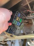
I am thinking the plastic fuse holder, a blade type block, but I can't see anything obvious there. I dont feel any hotspots (after turning the master off) elsewhere besides the dimmer fuse, and don't see anything obvious elsewhere. The dimmer switch does work when the headlights decide they do want to work, but this may also be a candidate for replacement, its the floor type switch that you step on.

I assume the blinkers and headlights are not working due to a short somewhere the prevents power from reaching them?

Any tips on things to look for in ferreting out this intermittent issue (the worst kind of issue)?
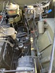
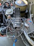
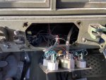
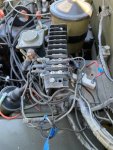
e1.jpg Engine compartment
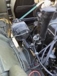
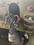
e2.jpg Ignition and other connections
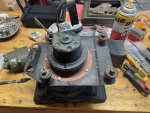
e3.jpg Delco Remx is model
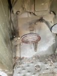
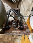
e4.jpg Foot switch for bright headlights
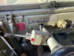
e5.jpg Turn Signal
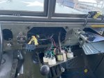
e6.jpg Instrument panel
e7.jpg Fuse block
 

John Mc

Well-known member
218
303
63
Location
Monkton, VT
When my headlights and blinkers started acting flaky, I traced it back to a bad socket in the connector that attaches to the three-lever lighting switch. I opened up the plug and cleaned the pin sockets and crimped one of them a bit so it would grab the pin more solidly. It was a bit of a pain to disassemble the plug, but it's been working well ever since I did so.
 

Redleg130

Active member
80
168
33
Location
Kansas
canofworms.gif

e9.jpg

e8.jpg

I am going through the likely suspects, the wire seems rotted in parts which may have been the issue. I may just have to redo it. That does not seem like a straightforward task. At least I got to drive it for a day 🥳
 

Redleg130

Active member
80
168
33
Location
Kansas
I am finding corrosion and wire rot in several areas. I disassembled the barrel connector and cleaned it thoroughly, I have seen some types of oils cause electricity jump in communications barrel connectors so getting it cleaned up should help, ill post photos of that process. It isn't easy, but possible.

Can anyone recommend 14ga wire that will be rugged and long lived? My reading has brought me to SXL stranded automotive primary wire as the description to look for, but if I am going to do this, I want to put in good stuff.
 

ODAddict

Active member
Steel Soldiers Supporter
107
218
43
Location
Charlottesville, VA
While I don't have a wire recommendation for you, I can offer some thoughts on my experience with similar issues.

My stock M37 had been under cover for most of its life. When beginning a rebuild last year, I discovered many problems with the wiring--most of it was age-related rot and cracking. Some of the problems were hidden--as in the headlight and other lamps and deep under the cowl. Some of it was similar as in your photos.

In other words, the problems in my truck were systemic. Doubtless, had I repaired the known issues, once I put power to the system, I would have discovered the unknown issues in a most unpleasant manner. If problems didn't manifest immediately, they likely would have become apparent at a bad time with the truck leaving me on the side of the road.

My solution was to purchase a new wiring harness. As I am in the process of a frame off restoration, anyway, installation will be fairly easy.

Looking a your challenges, it appears that a previous owner may have made some piecemeal repairs to solve his immediate problems which didn't address the systemic issues. That just kicked the can down the road.

It seems to me that you are looking at spending a lot or time playing wiring Whack-a-Mole. As Dennis G744 opined earlier in the thread, you may be better off starting from scratch with a new harness.
 

Rdinatal

New member
27
23
3
Location
Lake Normanopolis, NC
Can anyone recommend 14ga wire that will be rugged and long lived? My reading has brought me to SXL stranded automotive primary wire as the description to look for, but if I am going to do this, I want to put in good stuff.
I have great results with ANCOR Marine wires. Available via Amazon in various colors, lengths, sizes.
Have used ANCOR exclusively in boats and recently have done a lot of wiring in the M37.
 

Redleg130

Active member
80
168
33
Location
Kansas
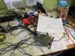
Me contemplating my wiring looms before cutting them open
eh.png

I may have found the foundational issue:
2ga.jpg
The 2ga wire coming from positive battery to solenoid (then to the rest from there) is worn through in 3 spots, the worst is shown above. It appears burned so this may have been the or a cause of flaky electrical systems.
I plan to replace this wire, reroute it so it isn't on things that move, tie it down better, and find some sort of protective conduit for it. I suppose garden hose or something like that could work.

I am mapping my wiring as it is, but it isn't matching really anything I have found, the closest being the M37 with signal stat diagram. It will take a bit of doing, but I am already learning a ton about vehicle wiring in doing this. Wiring Rescue - YouTube has been a good place for general concepts, not specific to my project, but a good introduction for someone who is new to it. My wife will be helping map to find where things go as I pull on them.
In progress diagram:
M37 12v.JPG

I was able to find the milspec 14ga wire (thank you for recommendations) and ordered a couple hundred feet of it. Also a huge handful of Packard rubber shell connectors from Big Mikes. I found harness tape which I hope will be better suited than electrical tape for bindings. Enough stuff to get me started anyway.

I also need to find a 6x6x4 box of some sort to go where the regulator I think is on factory M37. Its a shock mounted frame and should be a nice place for fuses and the ballast resistor (feeding the distributor and low volume fuel pump).
e2.jpg

Any wiring harness I can buy would have to be adapted extensively, so my plan so far is to rewire in place. Do a section at a time, with enough room to wrap when complete, then bind and secure well so its not all flopping around like it is now.
 

G744

Well-known member
Steel Soldiers Supporter
1,715
3,845
113
Location
Hidden Valley, Az
That Signal Stat turn signal control box is the very early attempt at such. Really junk, Don't even try to use that logic.

Too bad your rig is all 12V now. Sad.
 

Redleg130

Active member
80
168
33
Location
Kansas
That Signal Stat turn signal control box is the very early attempt at such. Really junk, Don't even try to use that logic.

Too bad your rig is all 12V now. Sad.
My apologies, I don't follow the first part of this. Do you mean the SignalStat is undesirable?

For the second part, I agree, but its too late now, so many parts are different (eg distributor assembly) it wouldn't be practical to go back to 24, even if I would prefer it.


As I am working on how I will do this, I have a couple questions. The three lever switch appears to have a feed, which then switches power to the various lights. I assume this works just fine given that seems to be common, is there any value in doing relays for some of the items, like headlights?

Can someone look over my diagram and evaluate if I am on the right track? There is a ballast resistor from the coil then to what I assume will be the keyed ignition, but I have not mapped it yet since I haven't validated it.

M37 12v.JPG

A friend of mine has a 4 way crimp tool, so I will be able to do proper crimps on the packard connectors without spending $500 for the tool thankfully. This thing - AF8 (dmctools.com)
 

Mullaney

Well-known member
Steel Soldiers Supporter
Supporting Vendor
7,716
19,765
113
Location
Charlotte NC
My apologies, I don't follow the first part of this. Do you mean the SignalStat is undesirable?

For the second part, I agree, but its too late now, so many parts are different (eg distributor assembly) it wouldn't be practical to go back to 24, even if I would prefer it.


As I am working on how I will do this, I have a couple questions. The three lever switch appears to have a feed, which then switches power to the various lights. I assume this works just fine given that seems to be common, is there any value in doing relays for some of the items, like headlights?

Can someone look over my diagram and evaluate if I am on the right track? There is a ballast resistor from the coil then to what I assume will be the keyed ignition, but I have not mapped it yet since I haven't validated it.

View attachment 920118

A friend of mine has a 4 way crimp tool, so I will be able to do proper crimps on the packard connectors without spending $500 for the tool thankfully. This thing - AF8 (dmctools.com)
.
A SignalStat is a good turn signal device.
Comes in 12v and 24v
 

G744

Well-known member
Steel Soldiers Supporter
1,715
3,845
113
Location
Hidden Valley, Az
I was referring to the military 24V Signal Stat box. It had to be used with a proprietary control handle.

I'm aware they still make a lot of good automotive items, jut not that one.
 

Redleg130

Active member
80
168
33
Location
Kansas
Can anyone identify this heater blower? There is no part number on this, and it isn't standard to the M37. It works but it sounds like it vibrates or shakes when starting up, it quiets down, but it may need service/replacement?

Heater.jpg

nearing completion on mapping. I got the AF8 tool, so I can start making replacement runs.

M37 12v.JPG

I found this box, which is 6x6x4 and should fit in the place where the regulator went. Hopefully it looks ok after paint, but it should give easy access to the fuses and bus connectors. https://www.amazon.com/Joinfworld-Clear-Cover-Electrical-Boxes/dp/B0CQQCPRM8
 

ODAddict

Active member
Steel Soldiers Supporter
107
218
43
Location
Charlottesville, VA
The blower doesn't look like anything I've seen mounted on an M37. But that opinion is worth just what you paid for it. :unsure:

Could it be part of a larger assembly for the stock hot water heater? Otherwise, it's anyone's guess.
 

Mullaney

Well-known member
Steel Soldiers Supporter
Supporting Vendor
7,716
19,765
113
Location
Charlotte NC
The blower doesn't look like anything I've seen mounted on an M37. But that opinion is worth just what you paid for it. :unsure:

Could it be part of a larger assembly for the stock hot water heater? Otherwise, it's anyone's guess.
.
Yes sir, it almost looks like a 80's Chevrolet defroster / heater blower.
 

Redleg130

Active member
80
168
33
Location
Kansas
I got the ground connections cleaned up, which actually wasn't straightforward to do. My truck is grounded through master switch, to the frame, then ground strap from frame to engine mount. You can get a wrench on the bolt at the frame, but its much easier with the muffler removed. I suppose that isn't a bad thing to do, my muffler and pipes are on ok shape, but the bolts had enough corrosion that putting fresh ones on was worthwhile. I also took the opportunity to clean, prime and paint (with the 2000deg rustolum stuff) the exhaust components to slow any corrosion. Not idea if that will last, but I suppose ill see.

The wire tags were tough to find, but I found them:
Wrap Around Tag – Style 1611 (M43436/3-1) – National Band and Tag Company
The company rep stated that you didn't need a tool to install, which I didn't believe really, but she was right, they just wrap around with finger pressure. They actually turn out nice and squared off without much effort. Once on, they seem to be quite rigid. They appear just like the ones installed on the M37 and M35a2 examples I have.
I ordered the 1/8in stamp set which seems to be the correct size for these tags
Fasteners & Accessories – National Band and Tag Company style 1571

My inaccurate stamping (first tag attempt) aside, I am happy with these tags
e10.jpg

Going through the electrics is tedious, but there is alot of corrosion I am able to clean up to get more years out of many of the items. The parking light above had significant rust inside but it works and I can get it cleaned up and protected.

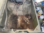
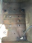
I also would never have looked in the battery compartment had I not made a project out of this, which has significant corrosion:
e11.jpg
Ill have to reinforce it somehow and do something to keep it from corroding further. Its rusted through slightly in a couple spots.

I am going to use Packard shell connectors since they seem more durable than the Douglass metal shells, but the crimping tool is insanely expensive. Fortunately, I was able to borrow one for awhile. The tool is a DMC AF8, but I suppose there are other 4 way crimps out there. Klein makes one that is less and Klein tools seem good, at least the tools I have.
e12.jpg
Using this tool is actually easier to use than what I imagined. The female Packard connector just barely fits through, but it does fit. It takes some oomphf to crimp, but the crimp is very solid. Im trimming the insulation just far enough that the wires can reach all the way through, hold in place and crimp. Wriggling the female connector out is difficult but it works. The male connectors are easier to do.

Slow going, but ill include photos of what I am doing and procedures for anything that isn't easy to do.
 
Last edited:

Redleg130

Active member
80
168
33
Location
Kansas
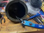
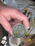
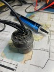
Two large hurdles cleared, cannon plug/connector and battery box

The cannon plug is a tremendous pain. The prestolite wire takes alot of heat and time to tin properly and that seemed to be the key in getting good connections with the solder cups. There is little space to work and seeing anything is a challenge. I cleaned the part with alcohol (sold as denatured alcohol fuel at home depot), and tinned the solder cups. The solder cups had garbage in them so I used a small torx screwdriver to ream them out before tinning.
e15.jpg

The wires must be combed and in proper order through the insulating part, any tangles and it will be a redo. Tin the wire without globs, but the entire bundle of wires should appear solid, although small enough to fit in the solder cup. Dab a bit of flux on the cup and wire and heat the cup, you should feel the wire drop in place when it melts. I had significant challenges with lead free solder, I couldn't get it hot enough. Lead solder worked.

e13.jpg

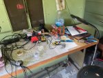
You need alot of light and magnification helped me, the magnifying LED lamp from JoAnns was very nice for this project. My spouse has this for her crafts, and I ended up getting one for myself:

e14.jpg

Each connection I made I used qtips and alcohol to clean the flux up. After all connections were made, I submerged/swished the assembly in alcohol to remove remaining flux.

I tested the connections with the three lever switch to ensure it behaves as it should, continuity when it should have it and none when it shouldn't

e16.jpg

Silicone grease helps the assembly to come together when its done.


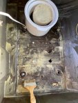
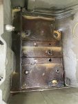
The battery box has some corrosion, I suppose taking this apart to clean every few years should be on my list of things to do from now on. On my farm, I have used beeswax to coat exposed metal and it works well, but those things aren't moving around so this may not work but ill try it and see what happens. I wanted to use something substantial for corrosion prevention as I don't want this area that is apparently very prone to corrosion getting worse. Paint does not seem to be sufficient in this space, but if there are better ideas, do please share.

Battery compartment cleaned out and scraped
e17.jpg

Applying melted wax from croc pot
e18.jpg

Use a heat gun to heat the metal so the wax adheres otherwise it just flakes off
e19.jpg

I tried a board to reinforce the metal, but it lifted the battery box to much so I had to abandon it unfortunately, I did keep the rubber spacers so there should be a bit of air getting to things now, it was just metal on metal before. There are spacers between each part, and on the underside where its held with a very large washer.

e20.jpg

With some help I got the bolts tightened down and should be ready to house the battery

e21.jpg
 
Top
AdBlock Detected

We get it, advertisements are annoying!

Sure, ad-blocking software does a great job at blocking ads, but it also blocks useful features of our website like our supporting vendors. Their ads help keep Steel Soldiers going. Please consider disabling your ad blockers for the site. Thanks!

I've Disabled AdBlock
No Thanks