• Steel Soldiers now has a few new forums, read more about it at: New Munitions Forums!

  • Microsoft MSN, Live, Hotmail, Outlook email users may not be receiving emails. We are working to resolve this issue. Please add support@steelsoldiers.com to your trusted contacts.

Ever see inside the Protective Control Box?

cwc

Active member
Steel Soldiers Supporter
307
153
43
Location
Sweeden, KY
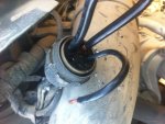
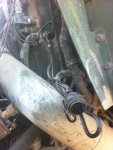
I had a failure of the PCB in my M925A1 last year. As part of the troubleshooting, I made some notes and took some pictures, attached. Mine was the type with a circuitboard. Hopefully the wiring diagrams will be helpful to someone in troubleshooting. I also put together a little troubleshooting guide, which goes to the extent of taking the box apart and checking the individual relays. The relays can be purchased individually fairly economically. In my case the main power relay was bad. I noticed that that model was an Ametek SAS-4418, which is a heavy duty intermittent relay, only rated to be energized 10 minutes at a time. So I replaced it with a SAS-4410, better rated for the application, i.e. continuous duty, more appropriate for the main power relay. Info at texasindustrialelectric.com.

PCB internals.jpgPower relay burned contacts.jpgPCB connection diagram.jpgPCB and wiring.jpg

View attachment PCB Troubleshooting.docx

As has been noted in other threads, the PCB provides protection against polarity errors and energizing the starter while the engine is running (signal from alternator to Terminal F). In the event of circuitboard failure, it would be pretty easy to rewire the box to bypass the circuitboard and directly energize the relays from the inputs to the box, but then those protections would be gone.


As far as emergency bypassing in the event of failure, you can connect the C & D terminals, the large wires, to replicate the function of the main power relay, then just jumper the starter. You also need to power the fuel solenoid to make the truck run, which can be done with the normal "RUN" switch position on the ignition switch once the main power relay is jumped. Keep in mind that alternator output will go through the jumper so it needs to be substantial. Just for kicks, I made a jumper out of 1/4" steel tubing, stuck it in the PCB plug sockets for Terminals C&D. Ignition switch on, then short the jumper to Terminal B (wire 74) with a screwdriver, the truck fires right up. Just keep in mind the jumper is electrically hot, and be careful handling it especially in the rain; 24 VDC can shock under the right conditions. See picture:

PCB connector with jumper.jpg

It seems the PCB enclosures may be put together a couple of different ways. I cut mine apart with a thin cutoff wheel in a side-grinder, then tack-welded it at four locations and JB-welded the gap all around.
 

TexAndy

Active member
1,427
16
38
Location
Bee County, Texas
I had a failure of the PCB in my M925A1 last year. As part of the troubleshooting, I made some notes and took some pictures, attached. Mine was the type with a circuitboard. Hopefully the wiring diagrams will be helpful to someone in troubleshooting. I also put together a little troubleshooting guide, which goes to the extent of taking the box apart and checking the individual relays. The relays can be purchased individually fairly economically. In my case the main power relay was bad. I noticed that that model was an Ametek SAS-4418, which is a heavy duty intermittent relay, only rated to be energized 10 minutes at a time. So I replaced it with a SAS-4410, better rated for the application, i.e. continuous duty, more appropriate for the main power relay. Info at texasindustrialelectric.com.
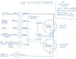
View attachment 497104View attachment 497105View attachment 497106View attachment 497107

View attachment 497112

As has been noted in other threads, the PCB provides protection against polarity errors and energizing the starter while the engine is running (signal from alternator to Terminal F). In the event of circuitboard failure, it would be pretty easy to rewire the box to bypass the circuitboard and directly energize the relays from the inputs to the box, but then those protections would be gone.


As far as emergency bypassing in the event of failure, you can connect the C & D terminals, the large wires, to replicate the function of the main power relay, then just jumper the starter. You also need to power the fuel solenoid to make the truck run, which can be done with the normal "RUN" switch position on the ignition switch once the main power relay is jumped. Keep in mind that alternator output will go through the jumper so it needs to be substantial. Just for kicks, I made a jumper out of 1/4" steel tubing, stuck it in the PCB plug sockets for Terminals C&D. Ignition switch on, then short the jumper to Terminal B (wire 74) with a screwdriver, the truck fires right up. Just keep in mind the jumper is electrically hot, and be careful handling it especially in the rain; 24 VDC can shock under the right conditions. See picture:

View attachment 497102

It seems the PCB enclosures may be put together a couple of different ways. I cut mine apart with a thin cutoff wheel in a side-grinder, then tack-welded it at four locations and JB-welded the gap all around.
That is awesome dude, thanks.
 

Tornadogt

Member
720
6
18
Location
Adkins, Texas
I had a failure of the PCB in my M925A1 last year. As part of the troubleshooting, I made some notes and took some pictures, attached. Mine was the type with a circuitboard. Hopefully the wiring diagrams will be helpful to someone in troubleshooting. I also put together a little troubleshooting guide, which goes to the extent of taking the box apart and checking the individual relays. The relays can be purchased individually fairly economically. In my case the main power relay was bad. I noticed that that model was an Ametek SAS-4418, which is a heavy duty intermittent relay, only rated to be energized 10 minutes at a time. So I replaced it with a SAS-4410, better rated for the application, i.e. continuous duty, more appropriate for the main power relay. Info at texasindustrialelectric.com.
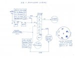
View attachment 497104View attachment 497105View attachment 497106View attachment 497107

View attachment 497112

As has been noted in other threads, the PCB provides protection against polarity errors and energizing the starter while the engine is running (signal from alternator to Terminal F). In the event of circuitboard failure, it would be pretty easy to rewire the box to bypass the circuitboard and directly energize the relays from the inputs to the box, but then those protections would be gone.


As far as emergency bypassing in the event of failure, you can connect the C & D terminals, the large wires, to replicate the function of the main power relay, then just jumper the starter. You also need to power the fuel solenoid to make the truck run, which can be done with the normal "RUN" switch position on the ignition switch once the main power relay is jumped. Keep in mind that alternator output will go through the jumper so it needs to be substantial. Just for kicks, I made a jumper out of 1/4" steel tubing, stuck it in the PCB plug sockets for Terminals C&D. Ignition switch on, then short the jumper to Terminal B (wire 74) with a screwdriver, the truck fires right up. Just keep in mind the jumper is electrically hot, and be careful handling it especially in the rain; 24 VDC can shock under the right conditions. See picture:
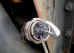
View attachment 497102

It seems the PCB enclosures may be put together a couple of different ways. I cut mine apart with a thin cutoff wheel in a side-grinder, then tack-welded it at four locations and JB-welded the gap all around.
All this information was very helpful, Just to add a bit to it on Emergency Bypassing or Testing.

View attachment 520897
These jumper wires are Copper 4 awg. about 6-8 inches long for main C to D terminal / 8 awg. Copper 4-6 inches for the Starter jumper Terminal B (Momentary for starter engage) They can be gotten from Home Depot / Lowes.
IMG_0719.jpg
In this photo you can see them installed.. I pull the C or D wire out just a bit to expose some Copper and jump The B wire to it, once the truck is started push the C and D terminal flush with the wire insulation for safety and you can remove the B terminal jumper wire completely until you need to start it again.. Follow the starting procedure stated in the above post.

IMG_0720.jpg
Just a Note if your PCB is removed from the truck you will need to reattach the ground wires to one of the PCB mounting bolts as seen in the top part of this photo.
I will be keeping a set of these in every truck I have and on Recovery trips for sure.

Hope this helps.....
 

plode

Member
270
3
18
Location
South Jersey
Here's the inside of my PCB:
20150111_145742_zpsh8x4nzhg.jpg

Have we established a way of getting rid of the circuit board? I've seen some very clean looking boxes with just the two solenoids and a couple of diodes attached to them.
With my truck, the main power switch would activate the one solenoid just fine, but the run switch activated solenoid wouldn't work. Tap on the PCB box with a hammer and it would come to life. So I figured since I've got the box open, I'll just replace both solenoids and if possible dump the circuit board in order to simplify things in there.
I went to NAPA for the solenoids, but they are a bunch of incompetent stupid people in there. They can't find parts like the older guys could. They rely on the computer and demand you tell them what make and model vehicle it is for. After explaining to them that their computer system isn't going to have a 5 ton military truck listed, they just tell you that they won't have it.

Any insight?
 

73m819

Rock = older than dirt , GA. MAFIA , Dirty
Steel Soldiers Supporter
In Memorial
12,195
327
0
Location
gainesville, ga.
First, if the master solenoid is working and the fuel solenoid is working when the start switch is ON, just start at the starter solenoid, run a wire straight from the run switch to the starter solenoid, this will by pass the black box, because the start circuit goes though the black box, looking for a closed neutral switch (939 only) and a closed oil pressure switch (no op = closed) then to the starter. this circuit is not needed, if you do not know if your engine is running or not and do not know if the truck is in neutral, you should not be in the truck in the first place.
In fact, the whole black box IS NOT NEEDED

Second, these engines are/were used in a LOT of cranes, these have a master switch that turns on a master solenoid which energizes everything and a starter BUTTON, no black boxes, VERY SIMPLE, I guess the thought that if you ARE smart enough to run a crane, you ARE smart enough to know if the engine is already running or not.

ALL that block box does is protect the truck from the untrained morons who can not tell if a truck engine is running, it is EAISER and most likely cheaper to use black boxes then to train, sorta like the data tag that says "do not use low reverse" the data tag is cheaper then teaching leadfoot gi how to drive a big truck.
 
Last edited:

rebelqwes87

New member
179
0
0
Location
Loganville, Ga
All this information was very helpful, Just to add a bit to it on Emergency Bypassing or Testing.

View attachment 520897
These jumper wires are Copper 4 awg. about 6-8 inches long for main C to D terminal / 8 awg. Copper 4-6 inches for the Starter jumper Terminal B (Momentary for starter engage) They can be gotten from Home Depot / Lowes.
View attachment 520898
In this photo you can see them installed.. I pull the C or D wire out just a bit to expose some Copper and jump The B wire to it, once the truck is started push the C and D terminal flush with the wire insulation for safety and you can remove the B terminal jumper wire completely until you need to start it again.. Follow the starting procedure stated in the above post.

View attachment 520899
Just a Note if your PCB is removed from the truck you will need to reattach the ground wires to one of the PCB mounting bolts as seen in the top part of this photo.
I will be keeping a set of these in every truck I have and on Recovery trips for sure.

Hope this helps.....
Is there a reason to not remove the C-D wire as well? I had to do this today and removed said wire to see what would happen. As far as I could tell nothing did.
 

todds112

Member
672
5
18
Location
Teton Valley, ID
Is there a reason to not remove the C-D wire as well? I had to do this today and removed said wire to see what would happen. As far as I could tell nothing did.
Looking at wiring diagrams it seems like it should have the same effect as turning off the main power switch (when everything is hooked up correctly).
 

firefox

General
Steel Soldiers Supporter
1,845
51
48
Location
Berkeley CA
Possibly the reason for the engine running starter protection has to do with
combat situations where all **** is breaking and you jump into a truck to
get out of Doge. You might be a little distracted.......
 

plode

Member
270
3
18
Location
South Jersey
First, if the master solenoid is working and the fuel solenoid is working when the start switch is ON, just start at the starter solenoid, run a wire straight from the run switch to the starter solenoid, this will by pass the black box, because the start circuit goes though the black box, looking for a closed neutral switch (939 only) and a closed oil pressure switch (no op = closed) then to the starter. this circuit is not needed, if you do not know if your engine is running or not and do not know if the truck is in neutral, you should not be in the truck in the first place.
In fact, the whole black box IS NOT NEEDED

Second, these engines are/were used in a LOT of cranes, these have a master switch that turns on a master solenoid which energizes everything and a starter BUTTON, no black boxes, VERY SIMPLE, I guess the thought that if you ARE smart enough to run a crane, you ARE smart enough to know if the engine is already running or not.

ALL that block box does is protect the truck from the untrained morons who can not tell if a truck engine is running, it is EAISER and most likely cheaper to use black boxes then to train, sorta like the data tag that says "do not use low reverse" the data tag is cheaper then teaching leadfoot gi how to drive a big truck.
The fuel solenoid isn't working. When I hit the box with the hammer, it kicks on then.

When I flip the main power switch, the gauges come on, and that's it. ABS, warning buzzer, and fuel solenoid kick on when I flip the run switch(when it works).
 

todds112

Member
672
5
18
Location
Teton Valley, ID
Bypass PCB??

Playing with the P2P wiring diagrams I see a possible bypass to the PCB that would retain using the starter switch to start the engine. I wanted to see if you folks that are a lot smarter than me agree or see a problem:

Here is the diagram with the PCB completely taken out of the picture. The main switch is on, and the starter is in "start" setting.

No PCB.jpg

This is with the terminals jumped (yellow lines). It looks like to me pushing the start switch would energize the neutral switch, which would energize the starter solenoid and start the truck. Normally the energized neutral switch would activate the solenoid in the PCB (E), which then activates the starter solenoid.

PCB Bypassed.jpg

Concerns: would the neutral switch be able to handle the current to energize the starter solenoid?

In theory, It looks like you would still use the power switch to turn the power on [Edit: power switch is bypassed, it would not have any effect. Main power would always be on], and still use the starter switch to start the truck. You would still have the neutral safety, but not the engine running or reverse polarity protection.

Please, wiring and electrical experts, let me know what you think.
 
Last edited:

Tornadogt

Member
720
6
18
Location
Adkins, Texas
Is there a reason to not remove the C-D wire as well? I had to do this today and removed said wire to see what would happen. As far as I could tell nothing did.
I Agree with what todds112 said, removing the C-D wire should kill all the gauges, CTIS, Horn, Ect.. It ,may not turn off the truck if the shut-off solenoid does not lose power. I am not sure if the shut-0ff solenoid is powered by the off-run-start switch or or the master power switch.


Added info..
Remember, if the truck running it is receiving power from the alternator not just from the batteries, that maybe another reason why it doesn't shut off when C-D jumper is removed. I have not tried to remove the C-D jumper while the truck is running, But I have used the Jumper wires on a truck with no batteries( I do mean No Batteries, not just dead batteries, I taped up the Positive ends so they didn't ground out). I slaved the truck to start it and then removed the slave cable the truck ran just fine only using the alternator power to power gauges and fuel solenoid.
 
Last edited:

Rockymyers

New member
5
0
1
Location
Alvin Texas
I have two PCB's that looks totally different that those shown, as well as the diagram. Both of mine have two solenoids, protective diodes on each solenoid, and each has another electronic component that I have no idea yet what they are. One could be a Zener Diode, and the other might be some other kind of diode. I am actually meeting with an electrical engineer tomorrow night to see if he can make sense of it. If it all works out I'll let everyone know what the verdict is.
Ultimately I had multiple electrical issues that were related to an indiscretion by the military installer of a power line to the vehicles warning lights. The power supply going to the CTIS was tapped into to power the vehicles rotating warning lights instead of them being put on their own line. Evidently the original PCB was defective due to corrosion, and was replaced with a new box. Proper care was not taken when it was installed and the power wire from the warning light switch to the warning lights had a PCB mounting bolt screwed through it. In effect sending it to direct ground. This was not a problem when there was no power to the switch due to the batteries being shot. Well I ran the vehicle just enough to build up some voltage so that when I turned the warning light switch on the overload fried the PCB and totally killed the power supply line to the CTIS and the parking brake warning light/buzzer. I have replaced the PCB with a new box and everything works but the CTIS and parking brake warning light/buzzer.
Although I have yet to find the probable circuit breaker in the CTIS power supply line that zapped during the overload, I am sure that there is one. If all else fails I can run a new power supply line and but a fuse in it.
 

rebelqwes87

New member
179
0
0
Location
Loganville, Ga
I did check all the gauges and they were all operational as well. I guess I just wanted to make sure there would be no ill effects. I wasn't sure if it would mess with the charging system not having that wire in place.
 

todds112

Member
672
5
18
Location
Teton Valley, ID
Remember, if the truck running it is receiving power from the alternator not just from the batteries, that maybe another reason why it doesn't shut off when C-D jumper is removed. I have not tried to remove the C-D jumper while the truck is running, But I have used the Jumper wires on a truck with no batteries( I do mean No Batteries, not just dead batteries, I taped up the Positive ends so they didn't ground out). I slaved the truck to start it and then removed the slave cable the truck ran just fine only using the alternator power to power gauges and fuel solenoid.
That makes total sense looking at the schematic. The power from the alternator (line 5) would be sending power to everything even if the C-D jumper is disconnected. The fuel solenoid is powered through the Run-Start switch, so switching it off would kill the engine regardless if the jumper is still in place or not.

No PCB.jpg
 
Top
AdBlock Detected

We get it, advertisements are annoying!

Sure, ad-blocking software does a great job at blocking ads, but it also blocks useful features of our website like our supporting vendors. Their ads help keep Steel Soldiers going. Please consider disabling your ad blockers for the site. Thanks!

I've Disabled AdBlock
No Thanks