• Steel Soldiers now has a few new forums, read more about it at: New Munitions Forums!

  • Microsoft MSN, Live, Hotmail, Outlook email users may not be receiving emails. We are working to resolve this issue. Please add support@steelsoldiers.com to your trusted contacts.

FLU419 SEE HMMH HME Owners group

The FLU farm

Well-known member
Steel Soldiers Supporter
3,356
1,360
113
Location
The actual midwest, NM.
I agree with fixing them, they should be straight. I just cant see how they could shorten the drive shaft. The torque tube would have to deform for that right?
Well, no, they don't shorten the driveshaft, but the do shorten the distance between the transfer case and pinion yoke when bent.
If they also shortened the driveshaft accordingly, I wouldn't worry about it.

Not that I know how much "give" there is in the 419's setup, but I have yet to see a driveshaft that doesn't have some sort of length adjustment capability in it that works. Does bent axle locating bars use that capability up? I don't know.

But I don't want to find out, which is why I spent a few minutes straightening mine. And I also know that bent tubing has little strength, and that Unimog put them in there (straight) for a reason.
 

Pinsandpitons

Active member
164
57
28
Location
Central Washington
A couple of quick observations;The restriction for the Backhoe raise and lower ram is at the valve I think. At least that’s where all the squealing seems to come from.
Second, while it puts a load on the engine I don’t think things happen any slower at normal engine idle. IOW, the high idle doesnt speed things up, so im not certain why the engineers thought there should be a restriction in that circuit, but I think it would be safe to move a little faster. In regards to some posts a while back I think flu farm has the right idea. If i ever get time ill enlarge that orifice a little rather than remove it all together.
 

alpine44

Member
403
17
18
Location
Asheville, NC - Elkton, MD
A couple of quick observations;The restriction for the Backhoe raise and lower ram is at the valve I think. At least that’s where all the squealing seems to come from.
Second, while it puts a load on the engine I don’t think things happen any slower at normal engine idle. IOW, the high idle doesnt speed things up, so im not certain why the engineers thought there should be a restriction in that circuit, but I think it would be safe to move a little faster. In regards to some posts a while back I think flu farm has the right idea. If i ever get time ill enlarge that orifice a little rather than remove it all together.
The manual does not show any orifice in that circuit. The noise you hear is from the over-pressure relief in the valve. I think the restriction are the hoses between valve and tilt cylinder, which are considerably smaller than all other hydraulic hoses on the FLU419.
 

Pinsandpitons

Active member
164
57
28
Location
Central Washington
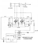
Hmmm, perhaps. Relief valves do tend to squeal more than orifices. And I just noticed that the in side of each of those valve spools has a check-valve, those could be the source also as they vibrate in their respective seats. The student handout does indeed show a .032 orifice at the cylinder, that was the original reason for the observation, but those usually can be put in-line any old place.
tilt&lock.jpg
1/4" lines would also slow things down, but I'm not sure they would turn the world to molasses or squeal like that.
 
Last edited:

alpine44

Member
403
17
18
Location
Asheville, NC - Elkton, MD
Hmmm, perhaps. Relief valves do tend to squeal more than orifices. And I just noticed that the in side of each of those valve spools has a check-valve, those could be the source also as they vibrate in their respective seats. The student handout does indeed show a .032 orifice at the cylinder, that was the original reason for the observation, but those usually can be put in-line any old place.
View attachment 733144
1/4" lines would also slow things down, but I'm not sure they would turn the world to molasses or squeal like that.
I will take the hoses off at both ends tomorrow and report my findings. The slow tilt is really annoying.
 
Last edited:

tennmogger

Well-known member
Steel Soldiers Supporter
1,579
546
113
Location
Greenback, TN
I am assuming the front PTO on a 406/416 is a hydraulic unit, yes? If so, is it run off the low-flow belt driven pump, or off the rear pump?
The front and rear PTOs on the 406/416 run off the transmission. A PTO box on the left of the transmission provides front or rear, or both, shaft engagement at either 540 or 1000 rpm. One model of PTO box is 540 only.
 

peakbagger

Well-known member
734
360
63
Location
northern nh
I am assuming the front PTO on a 406/416 is a hydraulic unit, yes? If so, is it run off the low-flow belt driven pump, or off the rear pump?
I believe the front PTO on the 416 is shaft drive right off the transmission. If you look at the grille you can see where the shaft would stick out if one was installed.
 

Foxyjosh

Member
53
0
6
Location
Northeast /OH
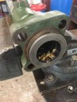
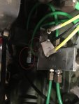
Hi. I know it's been a while but, time for an update: Transmission is reinstalled, engine is reinstalled, almost ready to put on the floor plate above the transmission however, a couple of lines are missing and I don't know where they go. The manual says to label the lines before removing them for ease of installation. Problem is, Uncle Sam never bothered putting the lines back on so I have no idea where they go. This is on the right side of the transmission where the shifter high/low range air shifter is.
 

Attachments

Last edited:

FarmMOG

Member
42
1
8
Location
Texas/Oklahoma
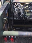
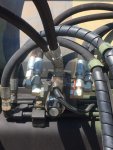
Greetings everyone. Just finished getting the front aux hydraulics installed. I used a splitter on the bucket tilt line to provide controllable hydraulic fluid to whatever implement is attached to the front quick disconnect. There is a second set of connectors mounted as well. These will be used later on to connect the electrically controlled front loader arms circuit to another splitter. This will allow full continuous flow either direction without having to hold a lever. I didn't connect it right now due to cost. I am finally able to use the tool circuit and can say the jackhammer works like a champ. I am trying to get a hydraulic tamper to use for a large fencing project on my dad's farm. I had to take the Mog to a hydraulic shop to fix the multiple issues that I was having, and all of the employees loved it. Several people apparently stopped by and tried to buy it from them, and were very disappointed it was not for sale. The more I use and customize it, the more I really like it. It sure has made a huge difference at the farm.

Forgot to add a safety message: If you are using the hydraulic tools, be sure to do a very good check of the whip attachments of the supply and return. Mine didn't seem bad at all, but only after about 7 minutes of use, the return side failed and my brother was covered with hydraulic fluid. Very thankful it was the return side and not supply side. It went from seep to large leak very fast, so whips for all three tools were replaced.


UNIMOG 1.jpgUNIMOG 2.jpg
 
Last edited:
Top
AdBlock Detected

We get it, advertisements are annoying!

Sure, ad-blocking software does a great job at blocking ads, but it also blocks useful features of our website like our supporting vendors. Their ads help keep Steel Soldiers going. Please consider disabling your ad blockers for the site. Thanks!

I've Disabled AdBlock
No Thanks