• Steel Soldiers now has a few new forums, read more about it at: New Munitions Forums!

  • Microsoft MSN, Live, Hotmail, Outlook email users may not be receiving emails. We are working to resolve this issue. Please add support@steelsoldiers.com to your trusted contacts.

Hollingsworth MEP-005a

Mullaney

Well-known member
Steel Soldiers Supporter
Supporting Vendor
7,716
19,766
113
Location
Charlotte NC
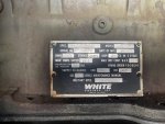
The oil filter housing is giving me a fit trying to get it to seal, but thank you! I will snag some pictures of everything else tomorrow! I can add some photos of the placards that the original owner sent me for the time being. The engine placard photo is a bit rough, I will have to get a better one tomorrow.
.
Definitely looks clean and pretty sharp!
 

ZRyals

Member
21
28
13
Location
Virginia
Its not a VR, its the A1, known as a "Thermal Watt Converter."

Have you downloaded the TM's? The MEP-004A and MEP-005A are same, same. Just a few more jugs on the 005.

Get some batteries charged up and then we can do some troubleshooting. This is a wonderful gen set. I hate the ASK, but thats from working on too many of them in the dark!

The Fault indicator panel is completely inop, so that will require some digging to diag and for whatever reason the stop-run-start switch becomes inop for a short time after a ride down the Road. Interesting bugs

The A9, Fault Indicator is normally a fuse bad, OR, open it up and see if the relay is in it. The A9 was more or less a pluck and chuck item. But not hard to fix.

The S2, Run/Start/Stop switch problem sound like loose C-Plug on thew control panel or maybe a loose relay, (Same kind as in the A9) on the A4 Control Panel Relay Assy.

Please take a boat load of pictures, good ones. Maybe we can see things you do not know about.

Do not worry about the A1 for the time being. Set runs fine when the A9 has a melt down.
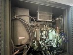
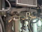
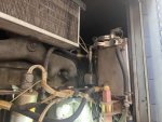
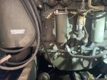
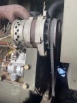
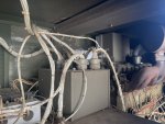
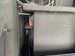
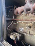
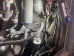
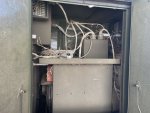
here are the rest of the photos as promised. Featuring the new oil filter housing, it came off of a dirt track car so that will make it faster right?
 

Attachments

ZRyals

Member
21
28
13
Location
Virginia
here are the rest of the photos as promised. Featuring the new oil filter housing, it came off of a dirt track car so that will make it faster right?
 

Attachments

Chainbreaker

Well-known member
1,796
1,992
113
Location
Oregon
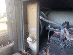
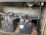
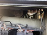
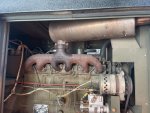
Looks pretty darn good on inside. Other than typical rust on the battery tray & a couple spots on the injector lines it's mostly just normal dust inside. There are a couple wires in one of the photos (Post#23 Pic #2) that were taped off. Wonder what those went to?

Interesting that Hollingworth built the genset in 1990, a late model by the way, & the White engine in your genset is a 1984. I guess either Hollingsworth or White had stockpiled an inventory of engines that were sitting somewhere in a warehouse that were used to fulfill future genset builds.
 
Last edited:

Guyfang

Moderator
Staff member
Moderator
16,768
24,094
113
Location
Burgkunstadt, Germany
In picture #6 I see a wire, (at least one) unhooked. I picture #8, I see a hack job, that's not Standard. It also explains, (I think) why the wire is unhooked.

This is in ref. to the first batch of pictures.
 

Chainbreaker

Well-known member
1,796
1,992
113
Location
Oregon
What do I see in Picture #8 of post 17? Looks like an aftermarket voltage regulator.
Yep, that is indeed what it appears to be! You can even see "Voltage" labeled on the rightmost trimpot. Also, might have something to do with the 2 wires (Post#23 Pic #2) I noticed that were taped off.
 
Last edited:

Chainbreaker

Well-known member
1,796
1,992
113
Location
Oregon
In picture #6 I see a wire, (at least one) unhooked. I picture #8, I see a hack job, that's not Standard. It also explains, (I think) why the wire is unhooked.

This is in ref. to the first batch of pictures.
Yeah, I too noticed that wire in Post #17 pic #6 at the corner of the terminal block that appeared to be positioned right above the terminal block corner hanging loose just above it with what looks like eyelet pointed down. Though after studying it a while I figured it was shadows playing visual tricks... that the eyelet was most likely bent at a right angle and connected to the TB and the shadows & corner of the TB inline was playing tricks... maybe not though? If it had been disconnected for whatever reason, I would have expected it to be taped off. But...that's assuming & with you also questioning it I agree it needs to be verified as connected.
 

ZRyals

Member
21
28
13
Location
Virginia
Yeah, I too noticed that wire in Post #17 pic #6 at the corner of the terminal block that appeared to be positioned right above the terminal block corner hanging loose just above it with what looks like eyelet pointed down. Though after studying it a while I figured it was shadows playing visual tricks... that the eyelet was most likely bent at a right angle and connected to the TB and the shadows & corner of the TB inline was playing tricks... maybe not though? If it had been disconnected for whatever reason, I would have expected it to be taped off. But...that's assuming & with you also questioning it I agree it needs to be verified as connected.
There was a regulator laying loose on that tray when I picked it up, I stuck it in a bag before I loaded it. There is one ring terminal pictured that is not connected to anything How should I proceed? Also, I was able to get the alternator charging, the fuse ends in had degraded, good to go now! I took the fault indicator out and looked at the board, the inboard side is full of rust in the board so I think that might be a lost cause to fix. seeking a replacement currently.
 

ZRyals

Member
21
28
13
Location
Virginia
There was a regulator laying loose on that tray when I picked it up, I stuck it in a bag before I loaded it. There is one ring terminal pictured that is not connected to anything How should I proceed? Also, I was able to get the alternator charging, the fuse ends in had degraded, good to go now! I took the fault indicator out and looked at the board, the inboard side is full of rust in the board so I think that might be a lost cause to fix. seeking a replacement currently.
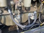
also, got some new hoses made for the spin on oil filter boss that don’t look quite so janky
 

Attachments

Chainbreaker

Well-known member
1,796
1,992
113
Location
Oregon
There was a regulator laying loose on that tray when I picked it up, I stuck it in a bag before I loaded it. There is one ring terminal pictured that is not connected to anything How should I proceed? Also, I was able to get the alternator charging, the fuse ends in had degraded, good to go now! I took the fault indicator out and looked at the board, the inboard side is full of rust in the board so I think that might be a lost cause to fix. seeking a replacement currently.
As for the "now verified" loose hanging wire... you need to look at the wire itself and get the wire # that is printed directly along the wire insulation. With that you will be able to identify where the wire should be connected by using the schematics in the TM.
 

ZRyals

Member
21
28
13
Location
Virginia
As for the "now verified" loose hanging wire... you need to look at the wire itself and get the wire # that is printed directly along the wire insulation. With that you will be able to identify where the wire should be connected by using the schematics in the TM.
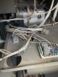
Upon further inspection I found the cannon plug that wire belonged to, aswell as another loose wire stuffed into the passthrough hole for the harness . Labeled D11G16 and D12G16 in a red-ish color. At first glance it looked like it was just part of the harness, until I moved it to get a wire number and the whole thing came out 🤦🏻‍♂️ To the TM’s!
 

Attachments

ZRyals

Member
21
28
13
Location
Virginia
Upon further inspection I found the cannon plug that wire belonged to, aswell as another loose wire stuffed into the passthrough hole for the harness . Labeled D11G16 and D12G16 in a red-ish color. At first glance it looked like it was just part of the harness, until I moved it to get a wire number and the whole thing came out 🤦🏻‍♂️ To the TM’s!
looking through the TM’s on here it looks like, D11G runs from P3-C to P9-C and D12G runs from P3-D to P9-D. Based on what I Am seeing in the parts manual and googling the national part number that is indeed an aftermarket VR and there is second plug on the OE VR, which I have not found in the diagrams yet. I‘m having a hard time reading some of the scanned sheets, so I may have to track down some paper manuals.
 

Guyfang

Moderator
Staff member
Moderator
16,768
24,094
113
Location
Burgkunstadt, Germany
Yeah, I too noticed that wire in Post #17 pic #6 at the corner of the terminal block that appeared to be positioned right above the terminal block corner hanging loose just above it with what looks like eyelet pointed down. Though after studying it a while I figured it was shadows playing visual tricks... that the eyelet was most likely bent at a right angle and connected to the TB and the shadows & corner of the TB inline was playing tricks... maybe not though? If it had been disconnected for whatever reason, I would have expected it to be taped off. But...that's assuming & with you also questioning it I agree it needs to be verified as connected.
The TB is TB16. It has two wire coming in from the static exciter, and two wires going out to the excitor in the main gen.
 

kloppk

Well-known member
Steel Soldiers Supporter
2,145
3,526
113
Location
Pepperell, Massachusetts
The aftermarket Voltage Regulator appears to be an ADVR-053.
The ADVR-053 has been superseded by the ADVR-054 and appears a bit different than the -053.

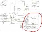
Oshkosh sold a kit using that module to replace the exciter. ---> Oshkosh Kit
Here is a schematic of how their kit was wired in. It included an SS500 Field Flashing module, relay, potentiometer and power resistor.
OSKOSH VR Schematic.jpg
 

ZRyals

Member
21
28
13
Location
Virginia
The aftermarket Voltage Regulator appears to be an ADVR-053.
The ADVR-053 has been superseded by the ADVR-054 and appears a bit different than the -053.

Oshkosh sold a kit using that module to replace the exciter. ---> Oshkosh Kit
Here is a schematic of how their kit was wired in. It included an SS500 Field Flashing module, relay, potentiometer and power resistor.
View attachment 872943
That is a beautiful diagram, appreciate that. Is the G I am seeing on my wires actually a faded B? Lol
 

jamawieb

Well-known member
1,437
556
113
Location
Ripley/TN
Your loose wire is going to the cannon plug for the flied flash. I've completed the conversion several times because the VR/Exciter box is the weak point in the system. But on my conversion I used a simple push button for the field flash instead of the complicated field flashing module. There is a write up I did on here about it. The advr-053 and 054 are supposed to be self-exciting with residual electricity in the gen head but it never worked for me. I had to introduce a field flash push button which sent 24v to the exciter in the head. Also the black gloo is from the Watt Transducer. I wouldn't worry about that because every unit I've dealt with had a bad watt transducer.
 
Top
AdBlock Detected

We get it, advertisements are annoying!

Sure, ad-blocking software does a great job at blocking ads, but it also blocks useful features of our website like our supporting vendors. Their ads help keep Steel Soldiers going. Please consider disabling your ad blockers for the site. Thanks!

I've Disabled AdBlock
No Thanks