• Steel Soldiers now has a few new forums, read more about it at: New Munitions Forums!

  • Microsoft MSN, Live, Hotmail, Outlook email users may not be receiving emails. We are working to resolve this issue. Please add support@steelsoldiers.com to your trusted contacts.

I beat the fuel fitting... And a thread for all the other mods to my deuce

lino

Member
148
2
18
Location
Wake Forest, NC
Do you have any an spot facers and cut straight thread then you can use a 815 an part and much less chance of buggering as no tapered threads just o ring seal on the aluminum part.

Are you profecient at g code?
I'm moderately proficient at g-code, but I primarily use the CAM module associated with my CAD tool to generate the code, it's parametric so the code updates as I change the model. I very rarely code directly.

I can certainly do spot faces and straight threads, the problem is there is only one port that would benefit on this filter housing. Just about everything on the truck is female NPT. All the ports on the booster pump, etc. In a couple places it's converted to AN or something else, but most often it's direct to DOT tubing, which is a pipe thread interface.

On this fuel filter bracket, there are 6 ports and 3 plugs (not counting the filter interfaces), 5 of the ports must be NPT (direct to DOT tube or pressure gauge), one port is AN, but if I'm doing that much NPT already, one more isn't a big deal. On the plugs, 2 are pipe, one is o-ring-straight thread. The two pipe threads need to be recessed below the surface, which is easy with NPT, and I'm already using that size pipe 4 other places...

If I could reasonably get rid of all NPT everywhere, I certainly would, but it's all over the vehicle already, and for better or worse, it's the standard interface on so many needed parts like DOT tube fittings and pressure gauges. A necessary evil.

ciao
lino
 
depending on the id and od of the tube you could run a adapter to flat face tube connector. That is if it would make things easier but I understand the desire to keep things as standard as possable.


In any case it looks like a nice setup, are you planning on marketing this item at all and if so do you have an idea of price?
 
Last edited:

peashooter

Well-known member
1,038
205
63
Location
Hanover, minnesota
Something I always intended to do but haven't is to make a 3d model and drawing of that specialty Master cylinder bracket for these late model airforce trucks. Since you are replacing the master cylinder, it might be worth trying to model it up in CAD. If you can find a way to reproduce that bracket for less than a couple hundred bucks then you would be able to supply the one needed part that is the most difficult to obtain for people who want to switch over to the dual circuit system.... just keep it in mind anyway.
 

lino

Member
148
2
18
Location
Wake Forest, NC
Something I always intended to do but haven't is to make a 3d model and drawing of that specialty Master cylinder bracket for these late model airforce trucks. Since you are replacing the master cylinder, it might be worth trying to model it up in CAD. If you can find a way to reproduce that bracket for less than a couple hundred bucks then you would be able to supply the one needed part that is the most difficult to obtain for people who want to switch over to the dual circuit system.... just keep it in mind anyway.
Can you elaborate? I'm not very familiar with the single circuit setup. What bracket is needed?

(also interested because soon I'll have the original MC and airpacks to sell...)
 

peashooter

Well-known member
1,038
205
63
Location
Hanover, minnesota
Can you elaborate? I'm not very familiar with the single circuit setup. What bracket is needed?

(also interested because soon I'll have the original MC and airpacks to sell...)
sure, the bracket that mounts your dual circuit master cylinder to the truck frame rail is a specialty item... it even has an arm on it to attach a pto winch lever too. This bracket is different than the ones on the single circuit trucks. This bracket is the "key" piece to being able to copy a dual circuit truck for the M35a2 trucks that have a clutch. The M35a3 trucks have a similar bracket but it doesn't have a PTO winch lever mount or provisions for the clutch pedal shaft.
 

Attachments

lino

Member
148
2
18
Location
Wake Forest, NC
So do you need just the circled arm added as a bracket to the single circuit stuff, or the whole pedal hinge assembly?
dual circuit bracket.jpg

I'll study the TM parts lists tonight to get a better idea of the differences between the single and dual circuit MC brackets.

ciao
lino
 

lino

Member
148
2
18
Location
Wake Forest, NC
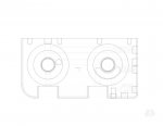
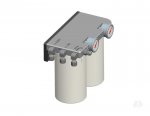
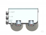
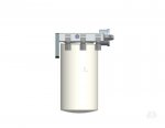
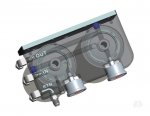
So I got thru a "rev 2" of the filter assembly tonight, based largely on Rustystud's comments that gauges facing the fender opening are desired. I like this version a little better anyway.
I've always been a little leery of how fragile the gauges can be and how far out there they hang, so these are recessed partially into the housing. I kinda like the look... Anyway, here are the renderings.
filter_plate_2.jpgfilter2_assy.jpgfilter2_assy2.jpgfilter2_assy3.jpgfilter2_assy4.jpg

And now off to measure some of the airpack bits...
 

rustystud

Well-known member
9,298
3,074
113
Location
Woodinville, Washington
Now that is a good look ! I agree the recessed gauges are much better. You need to build a prototype to find out how much it will cost to produce so I can buy one !!!
I also like that the bypass valve has an adjustable pressure range.
 
Last edited:

peashooter

Well-known member
1,038
205
63
Location
Hanover, minnesota
Now that is a good look ! I agree the recessed gauges are much better. You need to build a prototype to find out how much it will cost to produce so I can buy one !!!
I also like that the bypass valve has an adjustable pressure range.
I agree, this is a really nice and well thought out filter mount! I'll buy one also if I can afford it when you are ready to start selling them.
 

lino

Member
148
2
18
Location
Wake Forest, NC
Had a fairly productive day.

I hoped to have the brakes back together and bled, but (embarassingly) I snafu'd a brakeline and needed to buy some more copper-nickel brake line. Should have that tomorrow.

But I got the MC and the airpacks installed, as well as the reservoir, and it's all plumbed. (except MC to R. airpack)
IMG_1939.jpgIMG_1938.jpg

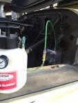
I'm also very happy with how the reservoir came out. I put in a vent manifold like Peashooter's as well. The reservoir has a quick disconnect plug (that seals on close) at the vent manifold. I can pop it out and it plugs into a mating fitting that I added to my power bleeder.
IMG_1925.jpgIMG_1930.jpgIMG_1929.jpgIMG_1932.jpgIMG_1931.jpgIMG_1927.jpgIMG_1926.jpgIMG_1923.jpg

At this point I had to stop on the brakes and moved on to fuel stuff...
-Next Post
 
Last edited:

lino

Member
148
2
18
Location
Wake Forest, NC
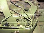
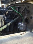
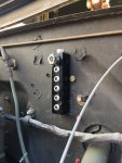
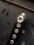
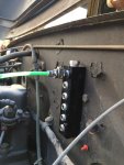
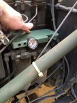
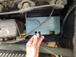
So on the fuel side. I did some test checks of the dual filter setup. I 3D printed part of it earlier this week and I wanted to see how it fit in the space.
IMG_1921.jpgIMG_1922.jpg

The length (longitudinal) is about right, but I'm going to make it a little wider.

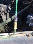
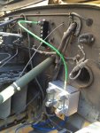
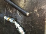
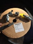
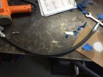
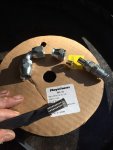
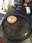
Then I started on the fuel lines. I'm using Aeroquip PTFE (Teflon) hose with stainless overbraid. I really like working with it. In the past, I've had trouble with SS braided hose acting like a bandsaw against anything near it, so I decided to cover the hose with heatshrink tubing this time. So far so good.
IMG_1933.jpgIMG_1937.jpgIMG_1940.jpgIMG_1936.jpgIMG_1935.jpg

I'm short some of the pictures for this, but I should have more tomorrow.
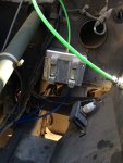
I've routed both the feed and return lines and they have one side fitted. I also mounted the first fuel filter in a new location. (pics later). I'm tracking hose lengths as well.

Feed line is rerouted to generally follow the same path as the return line.

More tomorrow.

ciao
lino
 
Last edited:

gringeltaube

Staff Member
Super Moderator
Moderator
Steel Soldiers Supporter
6,996
2,572
113
Location
Montevideo/Uruguay
So I got thru a "rev 2" of the filter assembly tonight, based largely on Rustystud's comments that gauges facing the fender opening are desired. I like this version a little better anyway....
Very nice setup!
Just don't forget the bleeder screw on top of the secondary FF. I think this is important to have.

2cents


G.
 

lino

Member
148
2
18
Location
Wake Forest, NC
I would advise making the filter bosses a 1"-14 thread. Lots of options for filter size and micron rating there, all the way down to 2 micron.
Yep. 1"-14 is the plan. They will accept WIX 33522 and 33339, and any other compatible.

I copied the filter interface geometry from WIX 24770

ciao
lino
 

lino

Member
148
2
18
Location
Wake Forest, NC
Very nice setup!
Just don't forget the bleeder screw on top of the secondary FF. I think this is important to have.
G.
I'm not quite clear on the purpose of this.
Is it a purge port for re-priming the system?

And were exactly in the circuit does it belong? At the exit of the final filter?

Thanks

ciao
lino
 

gringeltaube

Staff Member
Super Moderator
Moderator
Steel Soldiers Supporter
6,996
2,572
113
Location
Montevideo/Uruguay
I'm not quite clear on the purpose of this.
Is it a purge port for re-priming the system?

And were exactly in the circuit does it belong? At the exit of the final filter?

Thanks

ciao
lino
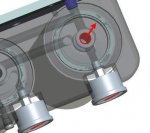
Correct, after changing the final fuel filter you don't want any air trapped there and eventually getting into the IP.

I would place that screw where the arrow is.


G.
 

Attachments

lino
Member
148
2
18
Location
Wake Forest, NC
So I have some more updates...
I've been working pretty steadily on the brakes, a civy receiver hitch/ winch mount, mounting a license plate, mounting LED taillights and indicators, reverse lights, and dealing with a blinker issue.

I'll cover the blinker stuff in this post.

So, when I got the truck, the blinkers worked fine, but one bulb (driving light) was out in one taillight. Seemed like a good excuse to switch to LEDs.
So I added a set of Grotes. worked great.

Since I had a set of taillight LEDs, it just seemed right that I should have front indicators in LEDs as well...

So a set of Trucklites showed up...

Somewhere in the process the blinker went out, and I'm not sure when or why. I first noticed "no worky" when I tried to see if the front indicators worked with LEDs while there were no taillights connected. It's not clear to me why that would have caused the flasher to go, but for whatever reason it did go out.
Also, all the LEDs on the truck right now have the internal load resistors, so they should be happy with any flasher unit and vice versa. Or not, as it were.

I then tested the fronts, as I knew the rears worked, and the lights were all good. Grounds checked and good too. everywhere.

Flasher tested bad. I didn't believe. Flasher tested bad again...

Looked at new flashers. Erik has one (that appears to be new style) for $42.
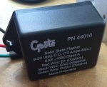
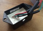
Grote makes a flasher unit available on Amazon for $32 delivered. Part number 44010 (there are threads on this). 9-32VDC max load 12 amps, standard or LED signal lamps. Same 3 wire configuration as stock setup.

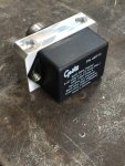
I went with the Grote. Here's what showed up:
IMG_2077.jpgIMG_2078.jpg
Note that I moved the wires from the side exit hole, and added some heatshrink in prep...

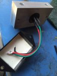
So, now to mount it. I saw a clever post where a fellow mounted one of these to the side of a gutted stock flasher unit and thus retained stock wiring, location etc.
So I gutted my broken flasher. I didn't like how things came apart, and one mount had been broken and only held in place by mounting screws, so that idea was canned.
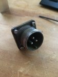
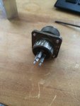
But I got the connector out of the assembly intact.
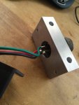
IMG_2075.jpgIMG_2076.jpg

So I decided to keep with the stock wiring theme. Solder cups on the connector would have made life simpler, but, so it goes...

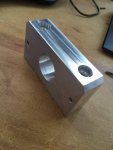
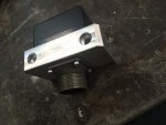
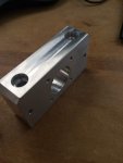
I machined a small bracket:
IMG_2073.jpgIMG_2074.jpg

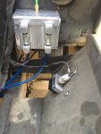
And I'm quite pleased with how it went together.
IMG_2083.jpgIMG_2082.jpgIMG_2080.jpgIMG_2079.jpgIMG_2084.jpg

And I'm happy to report that it works very well.
 
Top