• Steel Soldiers now has a few new forums, read more about it at: New Munitions Forums!

  • Microsoft MSN, Live, Hotmail, Outlook email users may not be receiving emails. We are working to resolve this issue. Please add support@steelsoldiers.com to your trusted contacts.

Kinda got carried away..... M1028 rebuild

Sharecropper

Well-known member
Steel Soldiers Supporter
1,836
987
113
Location
Paris KY
Thanks everyone for the well-wishes. Last wednesday afternoon at 4:15 I had a heart attack. Hit me like a ton of bricks and put me on the ground. Dialed 911 on my cell and the EMTs were here in 3 minutes, and transported me high-speed to the hospital. I had 2 arteries 99% blocked, which were opened with stents via heart catherization. I was discharged late Friday and am now recovering at home. I now have a sense of urgency to get my P400 / 700R4 installed.
 

Chaski

Active member
684
56
28
Location
Burney/CA
Well - that sucks.

Glad to hear you were able to summon help for yourself! Recover well - the project will be ready when you are. If I wasn't 2400 miles away I'd volunteer to come over on a future weekend to get the heavy work done.
 

Sharecropper

Well-known member
Steel Soldiers Supporter
1,836
987
113
Location
Paris KY
Well folks I survived another close one. I took it easy for a few days and now I'm back to almost-normal. Thanks everyone for the kind words and well-wishes.

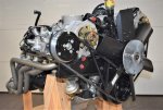
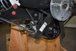
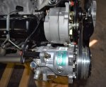
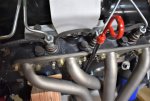
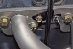
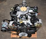
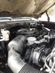
I jumped back on my P400/700R4 build and finished the front of the engine. Got the AC compressor mounted and belt tight. Re-installed the NOS fan clutch and fan with blue Lok-Tite. There's approximately 1/2" clearance between the fan and AC belt. Here are a few photos. Next I will figure out how to install an oil dipstick tube through those headers without touching or rubbing anything. Should be another edventure.
 

Attachments

Sharecropper

Well-known member
Steel Soldiers Supporter
1,836
987
113
Location
Paris KY
OK the next thing I need to do is to fabricate a custom oil dip stick tube to snake its way through the headers and into the hole on the side of the block. Problem is, I will need to fabricate the length of the tube so that the dip stick will "read" correctly when fully inserted into the tube and into the oil level. I tried a stock CUCV tube and dip stick, however the special cast aluminum P400 oil pan holds way more oil than normal. Based on a trial of the stock CUCV tube and dip stick, the oil level would be too high in the pan and right up under the bearing caps. I also have a HMMWV tube and dip stick, which extends a lot further out of the tube, however if this was used I believe the oil level would be too low.

So what I need to know is this - in an "at-rest" condition, where should the oil level be in the pan? I can and will fabricate the length of the custom tube so that the dip stick will extend the correct length out of the bottom of the tube and read correctly, but I need to know what is "correctly".

I wish I had a contact person at GEP I could call and ask, but I don't. And this is such an important issue, I need to get it right the first time.

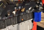
Here are a couple of early photos before dressing the engine, which shows the oil tube hole (red cap) on the side of the P400 girdle and the deep oil pan.

Thanks in advance for comments.
DSC_0273.jpgDSC_0270 (2).jpg
 
Last edited:

richingalveston

Well-known member
1,715
120
63
Location
galveston/Texas
https://www.jegs.com/i/JEGS/555/526...9613928&utm_content=Transmission & Drivetrain

I used a flex dipstick for my trans when I went to the 4l80e. you may be able to adapt this for your oil.
The bottom connection can be taken apart to shorten the tube section allowing you to customize the length of the hose and the hose will flex around all of your parts.
The dipstick for most of these is a simi-flexible cable with piece of metal on the last couple of inches, most of these cables can be adjusted by taking it loose from the top end and shortening the cable. At the top where the handle is for the dipstick, an allen screw holds the cable tight in the handle end.
Not sure all are made the same but if you can get the correct one of these then you can adjust the tube length and the rod length inside the tube to fit your needs.
you may have make an adapter for the end to fit the size hole you have in the block. it is probably not the same size as the transmission hole.
 

Sharecropper

Well-known member
Steel Soldiers Supporter
1,836
987
113
Location
Paris KY
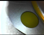
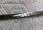
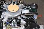
OK I made some progress. And also a discovery. I decided to run my endoscope down into the dipstick tube hole in the P400 block to see if there was any oil in the pan when it was delivered from GEP. Lo and behold, not only was there oil in there, but the level was right up to the internal baffle which is where it should be during normal operation.

So then I decided to modify a factory OEM 6.2 dipstick tube to fit in between the header tubes, leaving the length unchanged, to see where the oil level would hit on the factory dipstick. Another lo and behold, the oil level was perfect. So evidently, the correct amount of oil was shipped in the P400 oil pan from GEP. I will drain this factory oil and measure the liquid volume to obtain a starting point to refill with Rotella when I initially start up the engine. I am sure I will need to add oil to the overall quantity after cranking due to the volume requirements of the Spinner centrifugal filter and the forthcoming pre-oiler pump.

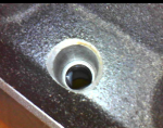
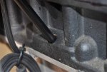
Also, I want to let everybody know that the hole in the block that the dipstick tube fits into is a 1/2" diameter hole drilled partly through, then a 3/8" diameter hole going on through into the oil pan cavity. The dipstick tube is 3/8" diameter with a "knot" around it to rest on the shoulder of the transition in the hole from 3/8" to 1/2" I was somewhat surprised that there was no seal at this junction, so prior to installing the dipstick tube I rolled a correctly-sized O-ring up over the knot on the tube and after inserting the tube as far as it would go, I then rolled the O-ring back down and tucked it into the gap between the 1/2" hole and 3/8" tube.
Here are a few photos -
 

Attachments

Andy01

New member
6
0
1
Location
Lake Havasu, Az
Great read! Looking forward to the finished project. I need to find another one and do a build. I'd like to find another one that is further along this time so I am not starting from the beginning like all of us have done to many times!
 

Tex68w

New member
17
0
1
Location
Texas
Just a heads up for those that missed out on the P400's. Mod Mafia in the Woodlands, TX has a few used P400's for sale.
 

Sharecropper

Well-known member
Steel Soldiers Supporter
1,836
987
113
Location
Paris KY
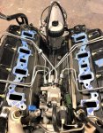
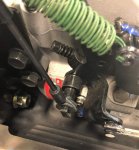
Made a little more progress. Getting things buttoned up and ready to install the new HMMWV intake. Finished plumbing the FFM. I decided to add a mechanical fuel pressure gauge so I installed a port fitting downstream from the filter. This -4AN hose will go to an isolator unit which I will mount on the firewall, then run a separate -4AN hose from the isolator to the mechanical gauge in the cab. I also installed a new NOS accelerator cable with a new C-clip on the injection pump throttle. Next to do - set the intake on.

Here are a few photos -
 

Attachments

Sharecropper

Well-known member
Steel Soldiers Supporter
1,836
987
113
Location
Paris KY
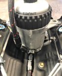
After 3 years, the P400 engine and 700R4 transmission are completely assembled and almost ready to install. Whew, what an adventure. I'm still working on a few minor things such as hooking up the 5 mechanical gauges, but this will be easy. I am particularly proud of the Spinner centrifical oil filter bracket and supply line. Here are a couple photos -
 

Attachments

Sharecropper

Well-known member
Steel Soldiers Supporter
1,836
987
113
Location
Paris KY
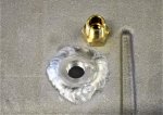
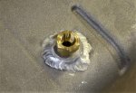
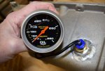
Well after much back and forth, I decided to install the oil temperature probe in the oil pan. The Autometer #5441 Oil Temperature mechanical gauge comes with a thermocouple line and probe designed to fit into a 1/2" NPT orfice, however on Autometer's site an alternative 3/8" bung adapter was available so I ordered one. I then ordered a 6160 aluminum 3/8" NPT bung from McMaster Carr and set into the process of installing the bung into the side of the P400 cast aluminum oil pan. The thickness of the cast oil pan is around .250, so I knew I had plenty of aluminum to weld-in the bung. I then determined the best location for the thermocouple probe, as well as which side of the engine would be the ideal side for the thermocouple line to exit the pan and run up to the gauge inside the cab. I already knew that the correct level of oil in the pan would be just under the oil pan baffle, so I decided to locate the probe about halfway betwen the top of the oil level and the bottom of the pan, on the drivers side.

The first order of business was to drill the side of the pan. Kind of a rush I might say, knowing that if I screwed up, the priceless and irreplaceable P400 oil pan would be forever ruined. But I got it done, and then took the pan and bung to my welder who is certified in welding aluminum. Within a minute or two he had the bung welded into the hole on the side of the pan as if it had grown there. Upon arriving back at my shop I test fit the Autometer 3/8" NPT adapter into the bung and decided to deepen the threads a bit so that the adapter would fully seat into the bung. I then test-fit the gauge thermocouple and concluded that everything will work as planned.

Here are a few photos -
 

Attachments

Sharecropper

Well-known member
Steel Soldiers Supporter
1,836
987
113
Location
Paris KY
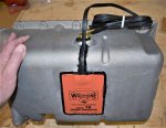
While I had the P400 oil pan off, I decided to go ahead and install a new Wolverine Model 16 oil pan heater. This oil pan heater draws 2.1 amps and will be wired together with the OEM engine block heater so that one plug will activate both heaters. I had to sand the aluminum P400 oil pan to produce an appropriate surface for the Wolverine to adhere to. The Wolverine is a peel & stick type of pad heater, and at first I was leery of the strength of the adhesive. However after sanding the pan, cleaning the sanded area with acetone, and sticking the pad, I learned of the strength of the adhesive. This sthing is stuck good. The Wolverine comes with a small tube of high temperature silicone sealant with instructions to run a continuous bead around the perimeter of the installed pad to prevent road water from penetrating the edge seal. I took it a step farther and siliconed the plug wire around the edge of the pan and zip-tied it to the temperature bung. This will prevent the weight of the plug wire from being stressed by gravity at the point where it goes into the pad. I am now ready to install this pan onto the P400 engine. Stay tund.
 

Attachments

sovei

New member
10
4
3
Location
north ga
Well after several months hiatus helping manage my wife's company, I am finally ready to get back to work on my P400 / 700R4 build and continue this rebuild thread, which has now gone on for nine (9) years.

The first order of business was to bolt down the new open-plane intake manifold. Since it had been a while since I had even looked at the engine on the stand, I decided to inspect things under the intake to make sure everything was tight and the way it was supposed to be. However the more I looked at that 1/4" rubber fuel line running from the fuel filter to the pump, the more i hated it. Having learned that one of the causes of rough starting/running was a leaky fuel line which sucks air into the fuel, and considering the fact that to repair a possible future leak in this section of hose would mean removing the intake, I decided to upgrade the fuel line to a -06 AN line and hose.

I removed the 1/4" rubber hose and factory ferrell from the injection pump. Then I removed the fuel filter and twisted out the pressed-in outlet ferrell. I then drilled and tapped the fuel filter to accept a 1/4" NPT pipe thread, and ordered the appropriate AN fittings and hose from Summit Racing. The inlet ferrell fitting in the injection pump is a 7/16"-24 inverted flare, and I needed a special fitting to transition from this to a -06 AN. Luckily, Leroy offers this fitting, so I ordered one from him (Thanks Leroy!). I then fabricated the proper length of -06 AN hose with the appropriate fittings and installed the assembly without a hitch. All fittings were torqued properly and now I don't have to worry about future leaks. Next step - install the intake.
Thank you Sir! I ordered the new fitting form Earls for my IP. I have upgraded to a Racor 20S Fuel Filter. Will wait till it gets here (the fitting) and order the correct hose to my filter. Tired of stinky fuel leaks! I also plan on swapping intakes to a 6,5 and possible the plenum to create an pseudo Cold Air Intake.20191216_133626.jpg cold air intake of sorts. Thanks again. Love your build!
 

Sharecropper

Well-known member
Steel Soldiers Supporter
1,836
987
113
Location
Paris KY
The 6.5 open plane intake will indeed improve air flow and capacity to the cylinders. Not sure you will need anything else.
That’s a clean looking engine!
 

Sharecropper

Well-known member
Steel Soldiers Supporter
1,836
987
113
Location
Paris KY
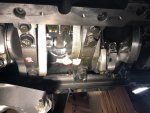
Well I believe I am finally ready to install the oil pan back on the P400. I got the bungs welded on each side of the pan, one for the suction pick-up for the pre-oiler pump and the other for the oil temperature gauge thermocouple. Also got the Wolverine oil pan heater installed the way I wanted. While I had the oil pan off the engine I decided to snap a few photos of the P400 underbelly showing the cast iron girdle and massive crank journals. Also shows the oil squirter that sprays fresh oil on the bottom of each piston and across the rod journal. The last image shows the cracked-rod technology used for all the forged connecting rods. Can you see the joint? Other upgrades of the P400 are forged crankshaft and pistons, ceramic coating on the piston tops, hardened valve seats, improved water flow, and a few more goodies I forgot. Should be a great engine.

IMG_3519.jpgDSC_0767.JPGDSC_0766.JPG
 

chevymike

Well-known member
596
463
63
Location
San Diego, CA
Damn! I have never wanted an engine more then I would love to have that one. One sexy beast! Too bad they did such a limited run of these and priced them accordingly....
 
Top