• Steel Soldiers now has a few new forums, read more about it at: New Munitions Forums!

  • Microsoft MSN, Live, Hotmail, Outlook email users may not be receiving emails. We are working to resolve this issue. Please add support@steelsoldiers.com to your trusted contacts.

M1078A1 "Pandora" Build | 2024-??? | ***Picture Heavy***

Ronmar

Well-known member
3,845
7,474
113
Location
Port angeles wa
I would remove that female QC from the wet tank drain. They are not meant to be out in the weather and will corrode quickly. They also tend to fill up and jam with road grime. Mine gave me nothing but problems, even when I slid a rubber boot over it. i would instead put in a ball valve and a male QC fitting.

A female QC there kind of defeats the purpose of being able to purge moisture from what is supposed to be a filter/separator stage in the system.
A male QC and a ball valve still serve this purpose as well as allowing you to charge or use air from the system. You just need a female-female adapter or female-female hose for the truck that you can keep stored out of the weather when not needed to use air from the truck…

Yours being an A0, I suspect the wet tank is not plumbed into the system correctly anyway. The Wet tank is supposed to act as a secondary cooler/dryer and settling tank so the brakes get the cleanest driest air. In order to serve in this capacity, 100% of the air must pass THRU the wet tank.

Well some bright light at S&S got it wrong, and since the diagrams in the manuals were probably created from the prototypes, they show it wrong in all the manuals that show tank service as well. The only place it is shown correctly is on page 34 of the schematics. Instead of running the air THRU the wet tank, they “T“d the wet tank off the dryer output line to the service tanks. Plumbed like this, i would say less than 1/5 of the brake air ever sees the inside of the wet tank.

Simple mistake, and lucky for us very easy to fix, you simply swap two of the line connections and their end fittings on the wet tank using the hardware thats already there.

Every A1 truck I have looked at is plumbed correctly with 100% of the brake air passing THRU the wet tank…

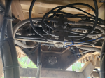
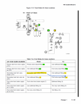
Here is how it looks from the factory and in the tank service diagrams in the manual.
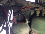

IMG_2650.jpeg


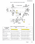
Here is how it should look, with 100% of the air forced thru the wet tank to get to the brake service tanks.
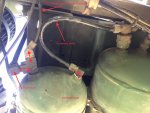

IMG_2663.jpeg
 
Last edited:

InvictusDecretum

Active member
108
210
43
Location
NC
I would remove that female QC from the wet tank drain. They are not meant to be out in the weather and will corrode quickly. They also tend to fill up and jam with road grime. Mine gave me nothing but problems, even when I slid a rubber boot over it. i would instead put in a ball valve and a male QC fitting.

A female QC there kind of defeats the purpose of being able to purge moisture from what is supposed to be a filter/separator stage in the system.
A male QC and a ball valve still serve this purpose as well as allowing you to charge or use air from the system. You just need a female-female adapter or female-female hose for the truck that you can keep stored out of the weather when not needed to use air from the truck…

Yours being an A0, I suspect the wet tank is not plumbed into the system correctly anyway. The Wet tank is supposed to act as a secondary cooler/dryer and settling tank so the brakes get the cleanest driest air. In order to serve in this capacity, 100% of the air must pass THRU the wet tank.

Well some bright light at S&S got it wrong, and since the diagrams in the manuals were probably created from the prototypes, they show it wrong in all the manuals that show tank service as well. The only place it is shown correctly is on page 34 of the schematics. Instead of running the air THRU the wet tank, they “T“d the wet tank off the dryer output line to the service tanks. Plumbed like this, i would say less than 1/5 of the brake air ever sees the inside of the wet tank. Simple mistake, and lucky for us very easy to fix, you simply swap two of the line connections on the wet tank using the hardware thats already there. Every A1 truck I have looked at is plumbed correctly…

Here is how it looks from the factory and in the tank service diagrams in the manual.


View attachment 924243


Here is how it should look, with 100% of the air forced thru the wet tank to get to the brake service tanks.


View attachment 924244
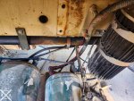
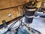
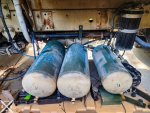
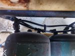
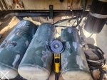
Thank you for bringing this to my attention ! I just went outside and checked. Despite mine being an early "A1" mine is plumbed differently than the A0. It has the air dryer/unloader going in to the front port, and the rear port to the service tanks (along with another thin line I did not trace)

20240525_141816 export edit.jpg

20240525_141903 export.jpg

FWIW that female QC is only on there to charge the truck with air from my garage compressor while I work on it. When I service the air brakes and replace all the 20yo air lines, I have the original drain valve to put back on there along with a Purest air dryer. I want to plumb in a female QC or two somewhere protected but will also put a ball shutoff valve before it/them after your warning. I've never had an issue with these Milton ColorFit Coupler & Plug Kit - Red-1/4" NPT, 14-Piece but I put a generic brass one on the wet tank since it wasn't permanent. This one has lived on that ARB manifold in my 2.8L Duramax Colorado for 5yrs or so without issue, but it is in the engine bay.


20210910_150634.jpg

This is my first air brake truck, and watching a YouTube couple almost get stranded in their unimog w/ air over hydraulic... I came to the following realizations:

  1. When you have an air leak on a straight hydraulic brake truck's On Board Air (OBA) you can't fill up tires/river floats as fast-if at all.
  2. When you have an air leak on an airbrake truck... You're a word that is prohibited on these forums but can be any part of speech.

@Ronmar any idea why the tanks are supposed to be drained in that order ? middle, front, rear/wet ? Batt box lid says "Drain tanks in sequence"

20240524_162440 export.jpg
 
Last edited:

Ronmar

Well-known member
3,845
7,474
113
Location
Port angeles wa
Cool, thats how it is supposed to be, all dryer air passing thru the wet tank. Like I said, I havn't seen an A1 plumbed incorrectly yet:) I think whoever was assembling them realized their error and just started assembling them correctly at some point, but didn’t bother announcing their error which would have forced them going back to fix all the previous trucks, and alter the manuals(a relatively big deal)… I have seen no tech bulletins published indicating this ever happened.

It’s not a horrendously big deal if your dryer is working properly, and not being overworked by excessive leakage. But it would help contain a dryer failure to the wet tank. i have a friend who missed service on and had a purest dryer cartridge fail/rupture internally and deliver filter media downstream.

If you have a 3126 and a circuit board power panel, but no battery disconnects or LBCD, I call those an A0.5…

aux systems that use air:
ctis. Supplied from the wet tank protection valve(large line).
fan control(and mid axle power divider lock). Typically tapped off ctis air in the cab.
cab suspension, small line split off from the ctis line just after the wet tank protection valve, runs over to the hydraulic manifold valve block
air for air op hydraulic pump. Comes from a remote control valve Td off of the service brake tanks, over to the hydraulic manifold valve block. The remote control valve disables the AOP supply whenever park air is applied(releasing park brakes).

I wonder what that little line is on the wet tank output to the service tanks? I am not aware of any other systems that use air…

i did a video on removing the AOP remote control supply valve from the service tanks as I did away with the AOP system entirely. I wonder whats on the inboard end of your service tanks, and if they drew AOP air from there. Thats not a lot of air. Two full service tanks can lift the cab twice. One full wet tank might struggle lifting the cab one time…

Here is a link to the AOP control valve delete…


InvictusDecretum

Active member
108
210
43
Location
NC
Cool, thats how it is supposed to be, all dryer air passing thru the wet tank. Like I said, I havn't seen an A1 plumbed incorrectly yet:) I think whoever was assembling them realized their error and just started assembling them correctly at some point, but didn’t bother announcing their error which would have forced them going back to fix all the previous trucks, and alter the manuals(a relatively big deal)… I have seen no tech bulletins published indicating this ever happened.

It’s not a horrendously big deal if your dryer is working properly, and not being overworked by excessive leakage. But it would help contain a dryer failure to the wet tank. i have a friend who missed service on and had a purest dryer cartridge fail/rupture internally and deliver filter media downstream.

If you have a 3126 and a circuit board power panel, but no battery disconnects or LBCD, I call those an A0.5…

aux systems that use air:
ctis. Supplied from the wet tank protection valve(large line).
fan control(and mid axle power divider lock). Typically tapped off ctis air in the cab.
cab suspension, small line split off from the ctis line just after the wet tank protection valve, runs over to the hydraulic manifold valve block
air for air op hydraulic pump. Comes from a remote control valve Td off of the service brake tanks, over to the hydraulic manifold valve block. The remote control valve disables the AOP supply whenever park air is applied(releasing park brakes).

I wonder what that little line is on the wet tank output to the service tanks? I am not aware of any other systems that use air…

i did a video on removing the AOP remote control supply valve from the service tanks as I did away with the AOP system entirely. I wonder whats on the inboard end of your service tanks, and if they drew AOP air from there. Thats not a lot of air. Two full service tanks can lift the cab twice. One full wet tank might struggle lifting the cab one time…

Here is a link to the AOP control valve delete…

My A0.5 does not have that Air Over Pump remote valve on the forward service tank, so maybe that line is the little one that comes off the wet output ?

Appreciate your posts here, here, and this video.

My forward tank looks similar to the end of your video, except it looks like my service tanks do not share air between each other. Those are one way valves on the input, correct ? Could the "A1" trucks only share air at the front and rear of the truck via checkvalves, off either tank ? That way if there is damage to either tank, it wouldn't depressurize both ?

On the forward service tank, the center is plugged and the other port is T'd off and the lines run to the front and rear of the truck.

The middle tank has two outputs, one large line running to the rear and one "regular" size line running to the rear & front.

20240525_153532 export.jpg


The "regular line" off the forward service tank running front and rear connects here in the rear:
1716667721900.png

Large line to the rear off center service tank connects here:
1716667804264.png

It's 90* outside, 100% humidity, and there is a swarm of mosquitoes out so I didn't follow the lines any further, but I absolutely will in the future to decode the A0.5 air system...
 
Last edited:

InvictusDecretum

Active member
108
210
43
Location
NC
Seems like the tanks are only tied together at the front and rear of the truck; there is no tank to tank transfer on the A0.5/A1. As best I can tell the front brake hose routing is the same on the A0 and A1... but wont find out for sure until I pull the bed... which is after battery box mod, then ecohubs, then cab stripping for heat/sound insulation + airconditioning + seats + carpet + kitchen sink.

I'll definitely make a visio diagram of what I find similar to the electrical diagrams I've been making. Mostly for my reference, but maybe someone else will benefit as well.

Thank you for all your time so far teaching me how to fish !

1716670490128.png

1716670358940.png
 

Ronmar

Well-known member
3,845
7,474
113
Location
Port angeles wa
If you don’t have the remote valve, I suspect that line on the wet tank output is indeed for the AOP supply.

The primary and secondary/rear and front systems are separated(required by Fed motor vehicle safety standards, FMVSS). Those one way checks on their inlet are supposed to keep them that way. You test this by filling the system till the dryer purges, then shutting down. Drain the primary tank. The secondary gauge should stay where it was. Then refill and repeat the process except drain the other tank. The other full tank should remain at pressure.

the lines running forward from each tank are each Td into and feed a 2way check-valve under the dash. That combined 2way output supplies park and trailer control air. This is also where the pri and sec gauge sensors sample their air. The other port on the T fittings connects to the pri and sec inputs to the pedal. The pedal is two mechanical pressure regulators in a common housing. The 2way check valve is supposed to allow the outputs of 2 separate systems to feed a single system without interacting/cross-feeding.

The secondary output of the pedal feeds right down to a QR valve behind the bumper and on to the front actuators., so pedal air feeds the front brake actuators directly.

Primary pedal output goes all the way back to the weight proportioner and the relay Valve.

The two smaller lines from the pri and sec tanks running aft are used for comparison and to feed the trailer controls. The larger primary line feeds the supply for the brake relay. Since the rear uses 4 larger cans, feeding all that air thru the pedal would creat a lot of lag. So they only really send a pressure signal from the pedal to the relay, adjusted/proportioned according to the weight in the bed, to activate the control the relay.

The relay in-turn is a remote pressure regulator. Whatever pressure it sees on its input, it copies on its output, using air from its supply port to supply(and drain) the rear brake cans rapidly. These different pathways serve to keep the brake response similar between front and rear axles, with the fronts probably slightly lagging behind the rears when applied, but releasing slightly faster than the rears when the pedal is lifted.

i did a video for a friend going over how the rear components operate.


InvictusDecretum

Active member
108
210
43
Location
NC
I managed to get some work done on stripping and painting the tanks and brackets. And then stripping and painting the brackets. And then stripping and painting the brackets. Turns out spraying rustoleum from the handheld airless HVLP sprayer (which has been awesome for small house reno projects) onto metal is not as easy as drywall and I'm not good at it. lol. I definitely improved but am not an expert, at all. I still get some texturing and I'm not sure why. That said, textured matte black paint on an army truck fits right in so eh.

20240526_174343 export.jpg

These abrasive paint and rust stripping wheels are freaking awesome. Legitimately the best thing I've ever used to get down to bare metal. Better than flapper wheel, better than wire wheels or cups... Blown away.

20240526_182302 export.jpg

20240529_125441 export.jpg

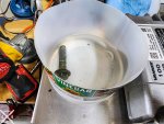
The bolts, like the tanks/bands, showed signs of a battery leak so I neutralized any acid with baking soda and acetic acid, then neutralized any rust with straight acetic acid, before taking them down to bare-ish metal and priming them the same gray I intend on painting the cab. I'm pretty sure that green is some kind of electrodeposition coating so even wire wheeling off the green should have left some coating, but eh. Fresh paint should also help.

20240601_162556 export.jpg
20240601_163525 export.jpg
20240601_165433 export.jpg

With the wife's help I got it mounted back up to the truck. Easily weighs 50# and there's no way I could have held that up and also given those 15/16 & 21mm nuts and bolts the ugga duggas by myself.

20240601_172601 export.jpg

The silver speckles are sanding dust from the side plates getting stripped down to bare metal. And yes, the overspray is driving me crazy but I was rushed when I was initially painting. After stripping down to bare metal, my friend called me with a dying alternator 200mi away. He made it 80mi toward me before his truck died and he coasted off I95, so I decided not to tape/barrier off the upper frame rail to save time and pack tools to grab him and his battery. Ended up swapping his alternator and putting a new battery in the next morning in a gas station parking lot.

I'm going to be painting the entire frame and just wanted to sand/rust prevent that part behind the battery box until I pull the bed off with a forklift to get full access. That is also when I will be replacing all the air brake lines and upgrading the air dryer, if I didn't cause a leak by pulling the tanks off/maneuvering them to paint/sand.

20240601_172556 export.jpg
 
Last edited:

InvictusDecretum

Active member
108
210
43
Location
NC
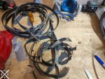
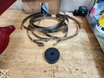
Was able to get a bit of small tasks done in the evenings this week. The original tank strap rubber isolators were crumbling where (I assume) battery acid leaked. Pretty much corresponded to where the CARC was broken/cracked/bubbling on the tanks. The paint on these bands was some kind of enamel, I assume, but came off easily with a coarse 4" angle grinder wire wheel. I tried those purple abrasive paint and rust stripping wheel at first but the angle was just annoying.

I ordered some new 5/16-24 nyloc SS nuts from McMaster Carr to replace the originals and cleaned the threads up with wire wheel.

And yes, I'm sure that abrasive blasting is probably the right answer for all of this vs angle grinder. I'm also sure I don't have a blasting setup in my garage and the cost of entry to them is quite steep. There are a couple sand blasting places I've looked at for the bigger stuff like the wheels off the truck, but small stuff I'll probably suffer through cleaning up myself until I make friends with someone with a blasting cabinet.

20240605_122149 export.jpg

20240605_124623 export.jpg

20240605_134639 export.jpg

20240605_155859 export.jpg

20240605_195651 export.jpg
 
Last edited:

InvictusDecretum

Active member
108
210
43
Location
NC
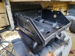
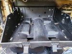
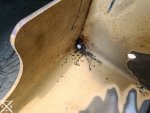
I also made a slight "mod" to the protective plate for the air tank drain valves. While using an abrasive paint and rust stripping wheel to clean the surface rust off of it, I noticed quite a bit of buildup in the corners. I drilled a 1/4" drain hole in each corner and deburred/filed it smooth to hopefully prevent rust spurs. I finished de-rusting as best I could before shooting a coat of black rustoleum on.

20240606_132630 export.jpg

20240606_132859 export.jpg

20240606_133147 export.jpg

20240606_134028 export.jpg
 
Last edited:

InvictusDecretum

Active member
108
210
43
Location
NC
Jumping back into this project after a too-warm-to-work-outside-summer.

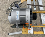
Ordered a 250A 24V Brushless J180 Long Hinge commercial alternator (Leece Nevill BLD4102M Idle Pro X), 1x Leece Neville Pulley (P/N K176105263S), and 1x Generic Pulley P/N 247750). Hopefully they ship early next week, but I still have a couple cables to make/terminate for the batt box anyway. And I need to chase down all the issues/problems I've caused rewiring it without adding in the variable of a new alternator, since the OE 100A dual voltage one was still working when I shut her down last... Also hoping I haven't nuked the ECM by letting it sit without batteries for 3mo.

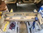
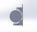
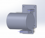
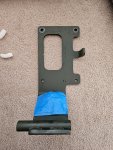
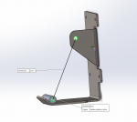
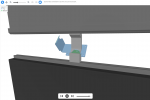
I'm going to design a replacement bracket in SolidWorks that converts the 3126 Short+Long pad mounts into a J180 Long Hinge. Open to suggestions but was planning on using the same simple construction method of rectangular steel parts full penetration welded through a 1/4 or 5/16 steel plate, but maybe add a rib or two since the bottom ear will be further forward and less supported due to the water pump cutout ? To support this part in Hike's pictures, found in his thread linked below:

1726878782967.png

1726878799660.png

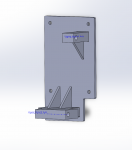
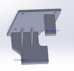
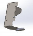
Basically something like this, where the back plate and ribs could be laser or waterjet cut, and the rectangular steel could be CNC profiled and drilled in 2 operations.

1726879182892.png

I specifically picked that alternator since it is similar/direct replacement to the one Hike installed (A0014740JB) in his thread here:

It also supposedly puts out 90% of it's 250A at idle

Huge thank you to Hike for all the pictures and info.
 
Last edited:

InvictusDecretum

Active member
108
210
43
Location
NC
Need to physically have the alternator to finalize the dimensions of it, which will drive the protruding post heights, but all the pieces seem easily machinable or cut-able, and weldable. I left 1/16" clearance for welds. Will 3d print it first, after I physically have the alternator, to check fitment before cutting metal.

1726894323359.png

1726894440063.png
.
1726894423251.png

1726894429449.png
 

GeneralDisorder

Well-known member
Steel Soldiers Supporter
2,034
5,224
113
Location
Portland, OR
I would copy the HIMARS design used on the C7. Fits both the Niehoff 260 and 300 (98 lbs). Only welding required is the pivot tube which is just a chunk of heavy wall tubing....

I have a friend making me 15 of them. Way simpler and more elegant. One laser cut piece of steel, 3 bends, and four small welds. A LOT cheaper to make too.

1000005609.jpg
 

InvictusDecretum

Active member
108
210
43
Location
NC
I would copy the HIMARS design used on the C7. Fits both the Niehoff 260 and 300 (98 lbs). Only welding required is the pivot tube which is just a chunk of heavy wall tubing....

I have a friend making me 15 of them. Way simpler and more elegant. One laser cut piece of steel, 3 bends, and four small welds. A LOT cheaper to make too.

View attachment 931941
That's awesome you're having an extra 14 made to (I assume) sell to other members looking to upgrade their alternators.

It is an interesting design. Skeletonized for weight, easy to make... and I am a huge fan of laser cut/CNC bent parts vs having to weld... Hm. I wonder if a hybrid approach would be best.

Caveat: I have a lot of respect and appreciation for your knowledge and contributions to the community. I left a lot of question marks in this post because I am 100% open to feedback along with explaining my current thought process.

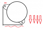
I would assume that some FEA went in to your HIMAR bracket, but I would think that long bottom arm would really only work for a swung mount alternator like the OE Niehoffs ? Vs the 6/12 o'clock ear orientation of a J180.

I think your mount can use such a long bottom arm since most of the weight of a swung alternator is on the bottom ears. That would explain why the top mount is much smaller and not reinforced for vertical loads. Without seeing the FEA sims, I think since the top alternator ear is clocked it has minimal vertical or lateral loads, being balanced between:

Belt tension + Alternator cant == clockwise rotation when the arm flexes​

If the bottom plate flexes, it's not as big of a deal and the belt tensioner would compensate for the static load of the alternator weight.

1726930964997.png

With the 6/12 o'clock orientation of the J180 mounting ears, I think the top ear shares <33% downward force, and I'll install the bottom bolt first to help with this. I copied the robust top mount of the A1 plate since it'll protrude further out to create clearance for the alternator (Or I suppose I could max out the distance on the bottom arm to cant the alternator inward but... I'd like to minimize the moment arm on the bottom since it carries most of the weight).
1726930158213.png

I also see there are multiple versions of the HIMARS mounting plate, with what appears to be a more robust/rigid mount. Do you know if yours was the V2 or V1 ? I have no interest in trying to find a place to bend 3/4-1" plate steel haha.

1726929576634.png
Alternator Bracket for 260 Amp Alternator FMTV A1 (easternsurplus.net)

At the risk of committing to a
 

GeneralDisorder

Well-known member
Steel Soldiers Supporter
2,034
5,224
113
Location
Portland, OR
The HIMARS bracket I showed above is the current version. The one in that Eastern Surplus listing is the old original 260A (fits the 300A as well) bracket from when the 260 was first introduced (and the one on my 2008 A1R from the factory) - the HIMARS 300A is heavier and it caused them to fail where the big "spring board" pivot block is welded to the back plate. I have talked to other Motorpool guys that have seen that older design crack at that point even with the 260. They order the HIMARS bent steel bracket to replace them.

I believe the plate thickness is 3/8" and his steel vendor that cut them also did the bends and my guy just had to send them the file and then weld on the tubes.
 
Last edited:
Ronmar

Well-known member
3,845
7,474
113
Location
Port angeles wa
I have always found welding easier than precise bends. They tend to be a little tedious, as I have never really been set up to do it(typically have to build the bending jig for the press). For a one-off, i can cut, position and weld much faster..
 

GeneralDisorder

Well-known member
Steel Soldiers Supporter
2,034
5,224
113
Location
Portland, OR
I have always found welding easier than precise bends. They tend to be a little tedious, as I have never really been set up to do it(typically have to build the bending jig for the press). For a one-off, i can cut, position and weld much faster..
For a one-off I would tend to agree and if the weight of the new alternator isn't crazy I'm sure that would work fine. The Niehoff 260 ( 72 lbs ) and the 300 ( 98 lbs ) are such that the inherent stresses and hardening in the weld areas cause failures. Yeah I know it can be annealed and it's down the welding skills, etc, etc. But the structural properties of a bent heavy gauge plate are just better in that regard. The end result will be lighter, simpler, and in all likelyhood (considering construction limitations) stronger.

You could still do it with careful planning and application of heat and a press. The bends aren't that sharp and I've bent plenty of steel plates with a vice and a torch and a couple of crescent wrenches. Mark it with a soap stone, heat along the bend line till it gets cherry red and put in your bend.

I had 15 made and the cost per piece from the steel vendor for materials, cutting, and bending was ~$75 each. Being the demand for the 260/300 setup is always high and the mount is the hard part to find I have no doubt I can recoup the costs and some profit on the extras. I have about 1/3 of them already spoken for and I'll retain a couple for myself in addition to the one going on my truck so I don't experience the cracked springboard mount being I'm running the 300 on my factory welded 260 mount at the moment.
 

InvictusDecretum

Active member
108
210
43
Location
NC
The HIMARS bracket I showed above is the current version. The one in that Eastern Surplus listing is the old original 260A (fits the 300A as well) bracket from when the 260 was first introduced (and the one on my 2008 A1R from the factory) - the HIMARS 300A is heavier and it caused them to fail where the big "spring board" pivot block is welded to the back plate. I have talked to other Motorpool guys that have seen that older design crack at that point even with the 260. They order the HIMARS bent steel bracket to replace them.

I believe the plate thickness is 3/8" and his steel vendor that cut them also did the bends and my guy just had to send them the file and then weld on the tubes.
Neither oshcut nor sendcutsend will bend anything thicker than 0.25" steel, but some quick chatGPT math says a 40# cantilever at the end of 1/4" A36 steel 3" wide and 7" long will deflect ~0.01" at 2.5G. And I can literally order this, blast 4x crappy welds on the tube and be done.

Dude, thanks.

1726948295250.png

1726948310743.png

1726948378940.png

1726948796786.png

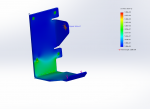
I'm not an engineer, simulation isn't my specialty, but I figured I'd play with it anyway.

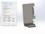
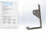
I fixed it via the 3/8" mounting holes and applied 100# of force where the 1/2"ID tubing will be. The upper 1/2" hole got 10# outboard and 40# downward. Seems like 1/4" A36 would be sufficient and maintained a 2x safety factor.

1726950400779.png

1726951671332.png
Shaded part is original, blue is the deformed with scale 1:1

I have always found welding easier than precise bends. They tend to be a little tedious, as I have never really been set up to do it(typically have to build the bending jig for the press). For a one-off, i can cut, position and weld much faster..
I'd trust a CNC bent part more than one of my non-professional welds, but thankfully MIG stands for Anybody Can Weld (The letters are unimportant).

These forums turned me on to OshCut for low rate parts, and their prices/services/UI are my preference now ! SendCutSend does bulk discounts better it seems, but that's not really applicable to me right now in my personal life.

1726950714581.png
 
Last edited:

InvictusDecretum

Active member
108
210
43
Location
NC
Yesterday I was able to finish making battery cables and tried to give her a start

20240427_154216 export.jpg
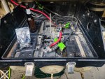
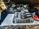
Before

20240928_183819 export.jpg
After. Turned out a little messier than I was hoping, and still need to cut down the length of the charger leads, but it does supply the correct power and the lid closes.

20240928_165859 export.jpg
Most of the remaining cables to be made were on the negative side.

20240928_151630 export.jpg
Frame ground goes to one of the air dryer mounting bolts.

20240506_172546 export.jpg
I bypassed the PPD with hydraulic crimped 4/0AWG butt splices, after I continuity checked and heat shrunk labeled them all.

Working on designing and CNC milling a heatsink for 2x 100A diodes I'm thinking of putting in the cabin behind the passenger kick plate, but with a master disconnect and 24v->12v Vanner doing all my conversion, I'm not too worried about reverse polarity.

20240928_181815 export.jpg
New 2/0AWG 24V alternator cable.


I shortened it a bit to prep for a commercial 24V alternator, which means it was a bit of stretch here haha. Clears the doghouse just fine and is clear of anything that gets super hot.

Screenshot 2024-09-29 104720 export.jpg
Nothing happened... whomp whomp.


I flipped the master disconnect switch on,verified voltages from the batteries looked correct, turned on both 12v and 24v circuit breakers, pressed the button... and nothing happened. Not even an attempt at a crank. I verified there was 24V at the starter, and remembered that fuzzytoaster had helped me start the truck by jumping the aux starter solenoid so I gave that a shot.

20240928_181738 export.jpg
Aux Starter Relay Jumping

Fired right up ! Barely needed to turn over, despite sitting for 4mo without running. The batts were disconnected but I didn't charge them, and I also didn't have to prime the fuel system. The biggest relief to me was that I hadn't killed the ECM by leaving the batts disconnected for that long...

Screenshot 2024-09-29 104817 export.jpg

I am so stoked that she's running again ! I let her run for about 15mins, didn't see any new leaks (still have a leak in the rear driver side of the trans pan), so I shut her down.
 

Attachments

aw113sgte

Well-known member
Steel Soldiers Supporter
634
947
93
Location
La Crosse, WI
I had 15 made and the cost per piece from the steel vendor for materials, cutting, and bending was ~$75 each. Being the demand for the 260/300 setup is always high and the mount is the hard part to find I have no doubt I can recoup the costs and some profit on the extras. I have about 1/3 of them already spoken for and I'll retain a couple for myself in addition to the one going on my truck so I don't experience the cracked springboard mount being I'm running the 300 on my factory welded 260 mount at the moment.
Can I reserve one of those? I'm running the 100amp and being kind to it but who knows... I thought there was a top bracket or something for the 260+ alts?
 

InvictusDecretum

Active member
108
210
43
Location
NC
Alright, new problem... My cab will no longer raise.

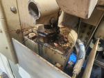
The cab will go up a small amount, the pin appears to retract, but the cab doesn't raise more than 0.5-1" we'll say. My wife and I were able to "help" lift the cab all the way up (Basically both of us overhead pressing from underneath the fender flares while I stretched to press the pump button). The cab lowered using the Air/Hydraulic Power Unit (A/HPU) just fine.


Troubleshooting taken:

0. Knobs were absolutely in correct positions (Top set to "Raise", bottom set to "Cab Tilt")​
1. Air pressure supplied by 35gal compressor via the wet tank @ ~125PSI​
2. Pin appeared to retract normally (1/4" ?)​
3. Alternated between Raise and Lower for 3-5 cycles of the A/HPU pump. No difference.​
4. The cab latch was sprayed with PB blaster​
5. Wife and I manually raised the cab (basically both of us overhead pressing from beneath the fender flares).​
6. Cab would lower using the A/HPU after we raised it, but would not go back up with A/HPU.​
7. Attempted to use hand pump (see below).​
8. Checked fluid level in reservoir. There are two rings on it, and it was up to the second one, but fluid looked slightly milky. Not ATF with water milkshake, but it was there.​

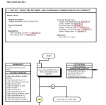
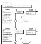
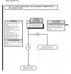
Dug into the TM 9-2320-365-20-2, Page 2-1960, and started following the charts... But have some questions. The title is cab tilt, spare tire, and suspension do not operate. I don't have a spare tire loaded right now but it would move the spare tire carrier up and down. Nonetheless, I followed them.

My questions:

1. What do y'all suggest I do ? Rebuild pump ? Rebuild manifold ?
2. Any recommendations on measuring hydraulic pressure or garage/backyard methods of determining if a hose is clogged ?
3. What does "Operate" mean in this context ? I get the normal ramming sound out of the A/HPU, and the backup pump does pump up and down. But the cab does not raise.

1727913832698.png

When I press the "Pump" button, it makes the normal sounds (cab tilt was operable 4mo when I shut her down). Regardless of "yes" or "no", Step10 seems to be the conclusion of this.

1727913926949.png

Attempt to use the back-up hydraulic pump resulted in same. Cab raised up maybe 1/2 to 1", then stopped raising. This started coming out of it, which is a similar color/consistency with what was in the A/HPU.

1727914362305.png

1727914633815.png

If I say that neither operate, I get Step 12, or possibly 11 (I have no method or knowledge of measuring hydraulic pressure currently).
1727915035099.png

Step 10

1727915179990.png

Step 10 basically says check filters, which there is a diagram on the next page, or replace the manifold, which I probably will not do since it would be with an unknown unit. I think I'd rather attempt to rebuild it instead... Helicool has a good video showing disassembly and some return hole poking.


Step 11
1727915398808.png

Step 11 basically says replace the manifold or the hydraulic hose indicated on the next page, but I can't measure hydraulic pressure.

Step 12
Step 12 flows similarly and ends in replace the air/hydraulic manifold after step13, if I have hydraulic pressure.
 
Last edited:
Top
AdBlock Detected

We get it, advertisements are annoying!

Sure, ad-blocking software does a great job at blocking ads, but it also blocks useful features of our website like our supporting vendors. Their ads help keep Steel Soldiers going. Please consider disabling your ad blockers for the site. Thanks!

I've Disabled AdBlock
No Thanks