• Steel Soldiers now has a few new forums, read more about it at: New Munitions Forums!

  • Microsoft MSN, Live, Hotmail, Outlook email users may not be receiving emails. We are working to resolve this issue. Please add support@steelsoldiers.com to your trusted contacts.

MEP-003A voltage and phase switch stuck

tennmogger

Well-known member
Steel Soldiers Supporter
1,579
543
113
Location
Greenback, TN
Working on a Sheriff's Dept gen set, MEP-003A. Has been sitting for years. Engine running now and sounds good but there are issues. The voltage and phase selection switch will not turn. Feel the spring load but the contacts do not jump to new positions. It seems the issue is mechanical and not in the electrical contacts, we hope. We have lubed the mechanical shaft parts in the front on the switch shaft, best we can get to it. Any suggestions? Is this a common failure? Changing that switch would be a nightmare.

There's no indication of AC output. There is DC output, mid green on the gauge. We haven't even started troubleshooting until the big switch works.

Other small issue is no 'start signal' to the starter solenoid. A jumper from 24v to the solenoid coil contact allows it to start (starting control switch held to "start' at same time).

Is that voltage/phase switch serviceable at all?
 
Last edited:

Scoobyshep

Well-known member
1,137
1,511
113
Location
Florida
Theres another thread on that in here somewhere. Iirc you can loosen the nuts on the back, use contact cleaner and work it loose. The other thread is well detailed.

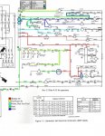
The start circuit is rather easy to trace. Follow the diagram on the top of the control cube (if not look in the -12 TM

Sent from my SM-G973U using Tapatalk
 

Ray70

Well-known member
2,595
5,914
113
Location
West greenwich/RI
Ah, Scooby Shep types faster than me!
You are correct all the way around! It's a common failure, it's a nightmare to change and it's a mechanical issue inside the switch.
Here's what I usually do:
Remove the side cover off the AC box.
Loosen the nuts on the ends of the rods holding the switch pack into 1 unit.
Spray contact cleaner and / or lubricant between the switch sections.
Then at the switch knob firmly rock the switch back and forth.
It may take a little while but 99% of the time the switch will suddenly free up and move as desired.
Once you get it where you want it.... LEAVE IT!
Note, be aware of the switch's normal function, it rotates beyond the ultimate stop position, then releases back and stops at 9:00 12:00 and 3:00
 

tennmogger

Well-known member
Steel Soldiers Supporter
1,579
543
113
Location
Greenback, TN
Perfect! Thank you. I will search for that thread some more. I had searched, really!

Update: found the threads! I had always included 003 in the search. Thread was on 002. Dumb computers shoulda known they are the same...

Great threads, thanks.
 
Last edited:

Guyfang

Moderator
Staff member
Moderator
16,776
24,103
113
Location
Burgkunstadt, Germany
K2 is the preheat relay.

"There's no indication of AC output. There is DC output, mid green on the gauge. We haven't even started troubleshooting until the big switch works."
These two functions have nothing to do with each other.
 

tennmogger

Well-known member
Steel Soldiers Supporter
1,579
543
113
Location
Greenback, TN
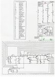
K3 is correct of course. I relied on memory. Post covid memory. Still chasing issues: K3 term X2 coil is not getting grounded to engage relay. Does have 24v to X1. Upper main terminal on K3 was loose too. Got that fixed. Tried following circuit on diagram on top of control panel but too poor quality. Home now to print out paper copy to take back tomorrow. Tnx for the help.
 
Last edited:

tennmogger

Well-known member
Steel Soldiers Supporter
1,579
543
113
Location
Greenback, TN
Looks like I need to check out S7, the Start Control Switch Assembly, that should be providing ground to K3 X2.

Edit: Guyfang, roger on that main circuit checked out good. Coil is not being enabled though, no ground, which S7 should provide.
 

tennmogger

Well-known member
Steel Soldiers Supporter
1,579
543
113
Location
Greenback, TN
The MEP003A is up and running! After burnishing Switch 7 there was start signal through K3 and the engine started fine. Output voltage is there, and adjustable. The Freq meter does not work though, and no DC output from the Freq Converter module. Not a show stopper. Many VOMs have frequency measurement.

The generator is on a trailer (M116 type?) to which a larger tank will be added, for multi-location use.

Thanks for the help.
 

Ray70

Well-known member
2,595
5,914
113
Location
West greenwich/RI
The frequency transducers on those machines are unreliable at best!
Either replace the gage with a direct read analog or digital gage ( remove the transducer and chuck it )
Or if you like the original gage look, you can pick up a newer style transducer that LITD found for $12 on ebay that will work, you just need to re drill the mounting holes.
I've used a few and they work great.
 

tennmogger

Well-known member
Steel Soldiers Supporter
1,579
543
113
Location
Greenback, TN
The new transducer was installed today. For anyone doing this job, unbolt the control box, unscrew two big connectors and a ground from the rear, and it's easy to get to the rear panel to drill new holes from the back. The screws from the original transducer (used with nuts) will screw into the captive nuts that are part of the new transducer.

However, still no 'frequency' indication on the meter. I had confirmed no DC output from the original transducer and made two assumptions (yeah I know): first that the meter was ok, and second that the transducer was bad. I failed to measure the AC voltage to the transducer. Today I didn't have my meter available, having switched vehicles and forgot to get it. Well, more testing tomorrow.

The schematic gets complicated. What is the voltage into the transducer supposed to be? Source?

BTW, the supposed manuals for the MEP-003 at https://www.steelsoldiers.com/threads/mep-003-tms-07082019.189242/ actually pull up MEP-803 manuals, all except the -12 manual which really is for the MEP-003A. Unless I am doing something wrong.
 

Chainbreaker

Well-known member
1,796
1,992
113
Location
Oregon
BTW, the supposed manuals for the MEP-003 at https://www.steelsoldiers.com/threads/mep-003-tms-07082019.189242/ actually pull up MEP-803 manuals, all except the -12 manual which really is for the MEP-003A. Unless I am doing something wrong.

...The schematic gets complicated. What is the voltage into the transducer supposed to be? Source?
Yep, using that link I got the same MEP-803 manuals you discovered under the MEP-003A TM listing. However, the good news is that Guyfang has the correct ones for the -003a on page 4 of the TM's postings.

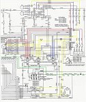
Looking at the schematic pg 53 the Hz meter is M3 and it connects to A3's +/- (transducer) which leads are connected to TB5 - pins 12 & 13 which then connect to transformers T1 & T2 tabs H1 & H2 and elsewhere along that circuit.

Edit: Those values feeding the transducer are supposed to read 120VAC. One thing to verify would be check those connections on the Terminal Block TB5 and Transformers T1-T2 and their tabs & elsewhere along that circuit to make sure they are all tightly screwed down to maintain continuity along that circuit.

Also, if your control Panel Box's 4 external "Vibration Damper/Isolators" are badly worn that box can shake/vibrate and eventually cause issues with wiring continuity, or worse the components themselves inside the Control Panel.
 
Last edited:

G744

Well-known member
Steel Soldiers Supporter
1,715
3,845
113
Location
Hidden Valley, Az
Most frequency transducers use a sample from one leg, usually 120VAC.

They supply a small variable DC voltage to operate the frequency (Hz) meter.

This is accomplished by using a resonant circuit and rectifier that ramps up the output voltage as the frequency goes up.

Unfortunately, many good Hz meters are ruined by someone hooking it directly to an AC output, thereby burning it out.

If the scale on the Hz meter has a "FS=100uA" or some such legend, it must be used with a proper transducer.

DG
 

tennmogger

Well-known member
Steel Soldiers Supporter
1,579
543
113
Location
Greenback, TN
Thanks for all the feedback! Guyfang, that schematic is different from the one I have in manual -12. Your schematic is SO much easier to interpret! Thanks. Next trip to the county shop in a few days. At $25 bucks in fuel to make that trip I don't go as often. This fuel situation stinks.
 
Top
AdBlock Detected

We get it, advertisements are annoying!

Sure, ad-blocking software does a great job at blocking ads, but it also blocks useful features of our website like our supporting vendors. Their ads help keep Steel Soldiers going. Please consider disabling your ad blockers for the site. Thanks!

I've Disabled AdBlock
No Thanks