I think I recall an old thread that you posted in Guy mentioning that the vibrations many times burned up the reed switches inside the float switch in either the closed or open state and it being a major headache. Did the army ever get this problem addressed or just replace them with new switches every time there was a problem?Is the float adjusted too low? Therefore vibrations every once in a while cause the float assy. To shake around too much?
-
Steel Soldiers now has a few new forums, read more about it at: New Munitions Forums!
MEP 802A Fix-up Thread
- Thread starter CallMeColt
- Start date

More options
Who Replied?- 17,493
- 25,873
- 113
- Location
- Burgkunstadt, Germany
As far as I can remember, there are at least 3-4 different manufacturers for the switch. But I cant say for certain that anything got improved, other then the float material itself. And that's only the covering, for the floats.
- 1,102
- 1,633
- 113
- Location
- Wilson County, Texas
I bottomed it out & then lifted it about 1/16th inch. I thought the same as you, so when I went in to check everything this time, I raised it up just a bit more & made sure it was as far away from the bulkhead of the tank as possible. Crossing my fingers!Is the float adjusted too low? Therefore vibrations every once in a while cause the float assy. To shake around too much?
robson1015
Active member
- 515
- 134
- 43
- Location
- New Concord, Ohio
Well let us know if this was the fix ..........thanx
- 1,102
- 1,633
- 113
- Location
- Wilson County, Texas
Will do. May be a few weeks before I go for an extended stay at my off grid place but it's going with me next time. Going to gun a 5,000 watt 220v heater to keep warm.Well let us know if this was the fix ..........thanx
- 1,102
- 1,633
- 113
- Location
- Wilson County, Texas
So, I did a weekend trip to my off grid place this past weekend. Clocked a little over 14 hours straight on the generator. No problems. Hopefully the "no fuel" ghost went away! Not the longest stay but it's the longest it's run without the fault. Installed a 5,000 watt heater for the winter. Pulls a 75% load. So, if it does run with a real light load, I can always turn the heater on to burn out any wet stacking before it gets bad.
- 2,586
- 2,290
- 113
- Location
- Efland, NC
FYI - Its more like a 100% load but only registering that amount due to the meter being calibrated with a power factor of 0.8.Installed a 5,000 watt heater for the winter. Pulls a 75% load. So, if it does run with a real light load, I can always turn the heater on to burn out any wet stacking before it gets bad.
robson1015
Active member
- 515
- 134
- 43
- Location
- New Concord, Ohio
Glad you got it worked out with the float adjustment...Guy is a valuable resource.....
- 1,102
- 1,633
- 113
- Location
- Wilson County, Texas
Yes, I did know that but didn't put it in my post. Thanks for pointing that out for those that may read this thread later on!FYI - Its more like a 100% load but only registering that amount due to the meter being calibrated with a power factor of 0.8.
- 1,102
- 1,633
- 113
- Location
- Wilson County, Texas
So, I'm up to 145 hours. Got some more problems.
Oil pressure gauge was dead. Easy fix... found a broken wire.
Wouldn't turn over when I got out to my camp this past weekend. disconnected the batteries & charged them up with my truck. Had to do this each time I wanted it to start. I knew this problem was coming since when the generator was sold to me it had two small 340CCA batteries that are meant for a small riding mower. Now even with both batteries fully charged, it does the "click" but will start itself up barley. Going to get the proper Optima batteries IF I can fix the next problem...
Went to run my 240v electric heater & it wouldn't start but seemed like it would try. Tried a microwave.... power was flickering. At this point I just shut it down & waited until I got back home to work on it in the shop.
I let both batteries top off the past few days on a charger. Still barley starts.
Found that L1 has incorrect voltage. I was going around 80 volts with it on the single phase, 240/115 volt setting.
Going to dig into the manuals now for troubleshooting... wish me luck!
- 1,102
- 1,633
- 113
- Location
- Wilson County, Texas
Voltage regulator & potentiometer all tested out okay. Fuse for the QUAD mod fuse is okay.
Found in 3 phase that the voltage is incorrect as well from L1.
The next stuff is testing things inside the generator alternator itself. I'm very intimidated by this... both because I fine the TM's generally confusing... & it seems like a lot of time involved. I don't have a lot of time.
Very discouraging. I've spent more hours working on this generator than it has run.
Considering just using 3 phase mode, moving L1 to L2, & turning up the voltage regulator. That should give me 220v. I don't like doing things the wrong way but I will need this $4,000 paperweight to do something for me!
Since the unit was giving proper output and then stopped, I would take the top off the gauge cluster to make sure all the connections are tight/clean. You will then be able to test the direct leads out of the generator to see if its the generator itself. It could be a dirty connection on S8 (reconnection switch)
- 1,102
- 1,633
- 113
- Location
- Wilson County, Texas
That's what I'm hoping... just a dumb loose wire or something like that. It's strange how it worked fine & then next time I started it, it didn't. Once I can pull the top off & look at everything, I will report back.Since the unit was giving proper output and then stopped, I would take the top off the gauge cluster to make sure all the connections are tight/clean. You will then be able to test the direct leads out of the generator to see if its the generator itself. It could be a dirty connection on S8 (reconnection switch)
I was able to use in in 3 phase mode, adjust the voltage, & it's running good. Ran it at 100% load for 20 minuets no problem. The % load meter reads higher in 3 phase mode I noticed... more like a 1 power factor.
- 1,102
- 1,633
- 113
- Location
- Wilson County, Texas
Okay, so I pulled the top cover off today to start digging. Everything looks fairly clean & noting obviously loose. It appears as if the coil lead wires going up to TBS have been messed with before making me think that someone has gone through the same tests that I am about to.
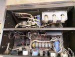
Did some searching on the forum & came up on this thread where someone had an issue with one leg putting out the wrong voltage.
https://www.steelsoldiers.com/showthread.php?180607-MEP-802A-voltage-readings-not-right
I first started with the voltage regulator testing... Section 2-27-2 of TM 9-6115-641-24, page 95 of .pdf file. All was within what it should be. I was a bit confused by step o... "o. If steps h. j, I and n are as Indicated above, AC voltage regulator IS defective and must be replaced" If they're as indicated above, then why does it need to be replaced? I'm guessing it is a typo & should say NOT as indicated above. Am I just being dumb?
I moved on to testing generator stator... Section 4-10-7 of TM 9-6115-641-24, page 221 of .pdf file. It has you reference table 4-1 at the beginning of the 4-10 section on page 217 of the .pdf file. The range on the stator leads should be between .3731 & .5047. Step g said to use a resistance bridge... I don't know what this is. The resistance I got between all the wire pares was .6 with both of my multimeters. This is high, but I don't know how to make my meters show a more accurate reading. When I change the setting, it gives me all zeroes. Tried with two good multimeters. Maybe me being dumb again? Moving to step h... I got a reading of 2.2. This is much higher than it should be. Steps j & k are good.
So, according to step i, the stator winding is open & must be replaced.
Please tell me I'm wrong!
I'm not sure what to test next.. or if there is anything else to even test.
After getting to this point, I stopped & typed this up. If the stator is bad...
- 1,102
- 1,633
- 113
- Location
- Wilson County, Texas
Okay, so I continued after work today digging in & found my problem... still doesn't answer why my ohms readings were so high but oh well.
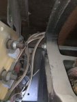
I found the wire broken at the ring connector on L1. I previously checked this by reaching behind & grabbing for loose wires. I ended up finding it when I removed TB2 & moved it to the side to get at the bell housing cover to look into the generator head for anything obviously loose or damaged. The wire was being held in place by the plastic insulator but the copper wire itself was separated & was lightly touching. I can see where it caused a lot of heat & the wires melted a bit.
So now I need to find a new cable end... not a big deal. Hopefully will get one today & fix the wire properly then bolt everything back together.
The batteries still need to be replaced but I'm hoping that I can get one more start up out of them to test everything properly.
Once I'm satisfied with the test, I'm going to buy two new Optima Group 51 batteries, make all new battery cables, & get some good mounting trays. I found some nice ones for $50 shipped each that will keep the batteries very secure.

Will post again once I get it all back together.

I found the wire broken at the ring connector on L1. I previously checked this by reaching behind & grabbing for loose wires. I ended up finding it when I removed TB2 & moved it to the side to get at the bell housing cover to look into the generator head for anything obviously loose or damaged. The wire was being held in place by the plastic insulator but the copper wire itself was separated & was lightly touching. I can see where it caused a lot of heat & the wires melted a bit.
So now I need to find a new cable end... not a big deal. Hopefully will get one today & fix the wire properly then bolt everything back together.
The batteries still need to be replaced but I'm hoping that I can get one more start up out of them to test everything properly.
Once I'm satisfied with the test, I'm going to buy two new Optima Group 51 batteries, make all new battery cables, & get some good mounting trays. I found some nice ones for $50 shipped each that will keep the batteries very secure.

Will post again once I get it all back together.
Last edited:
Chainbreaker
Well-known member
- 1,820
- 2,080
- 113
- Location
- Oregon
Good job finding that! Persistence in troubleshooting and Jamawieb's suggestion seems to have really paid off!
Last edited:
- 545
- 279
- 63
- Location
- Eubank, KY
An open stator winding would read infinite ohms in a pair of it were burned open and much lower if it were shorted.Okay, so I pulled the top cover off today to start digging. Everything looks fairly clean & noting obviously loose. It appears as if the coil lead wires going up to TBS have been messed with before making me think that someone has gone through the same tests that I am about to.
View attachment 761336
Did some searching on the forum & came up on this thread where someone had an issue with one leg putting out the wrong voltage.
https://www.steelsoldiers.com/showthread.php?180607-MEP-802A-voltage-readings-not-right
I first started with the voltage regulator testing... Section 2-27-2 of TM 9-6115-641-24, page 95 of .pdf file. All was within what it should be. I was a bit confused by step o... "o. If steps h. j, I and n are as Indicated above, AC voltage regulator IS defective and must be replaced" If they're as indicated above, then why does it need to be replaced? I'm guessing it is a typo & should say NOT as indicated above. Am I just being dumb?
I moved on to testing generator stator... Section 4-10-7 of TM 9-6115-641-24, page 221 of .pdf file. It has you reference table 4-1 at the beginning of the 4-10 section on page 217 of the .pdf file. The range on the stator leads should be between .3731 & .5047. Step g said to use a resistance bridge... I don't know what this is. The resistance I got between all the wire pares was .6 with both of my multimeters. This is high, but I don't know how to make my meters show a more accurate reading. When I change the setting, it gives me all zeroes. Tried with two good multimeters. Maybe me being dumb again? Moving to step h... I got a reading of 2.2. This is much higher than it should be. Steps j & k are good.
So, according to step i, the stator winding is open & must be replaced.
Please tell me I'm wrong!
I'm not sure what to test next.. or if there is anything else to even test.
After getting to this point, I stopped & typed this up. If the stator is bad...
Don't forget, the readings in that table are "temperature" dependent, they are not cut and dried for all conditions.
You might try pulling off the stator cover end and look at the visible windings for any indication of over heating.
I found indications of overhearing in one of my sets and am in the process of changing the stator.
- 17,493
- 25,873
- 113
- Location
- Burgkunstadt, Germany
Fix the cable. Test the set. If you still have problems, then look at the stator. Easy fix, quick repair. Those ring connectors often break or crack. Good job finding it. That's one thing I always checked for by running a set at night, or in a dark shop. When you see a arc/spark, you know there is a problem.
- 1,102
- 1,633
- 113
- Location
- Wilson County, Texas
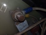
Repaired the broken wire connector & closed everything back up.
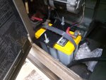
Picked up the proper Optima group 51 batteries. Didn't order the battery trays for now. May do it down the road along with making all new battery cables. I also made my own battery hold downs. Not super pretty but they work well. I also added a quick battery disconnect for when it sits for an extended period of time or if I need to put my trickle charger on either of the batteries.
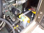
Tested it at a 5,000w 240v load for 1.6hrs. No issues at all except a little fuel leak around one of the injectors. It may have been doing this for a while.
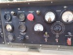
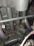
Thank you everyone for the help. Hopefully the next time I need to work on this will just be for the oil change!

Picked up the proper Optima group 51 batteries. Didn't order the battery trays for now. May do it down the road along with making all new battery cables. I also made my own battery hold downs. Not super pretty but they work well. I also added a quick battery disconnect for when it sits for an extended period of time or if I need to put my trickle charger on either of the batteries.


Tested it at a 5,000w 240v load for 1.6hrs. No issues at all except a little fuel leak around one of the injectors. It may have been doing this for a while.


Thank you everyone for the help. Hopefully the next time I need to work on this will just be for the oil change!
Last edited:
- 1,102
- 1,633
- 113
- Location
- Wilson County, Texas
Good idea to run in the dark & look for sparks!Fix the cable. Test the set. If you still have problems, then look at the stator. Easy fix, quick repair. Those ring connectors often break or crack. Good job finding it. That's one thing I always checked for by running a set at night, or in a dark shop. When you see a arc/spark, you know there is a problem.
- 112,579members
- 166,188threads
- 2,340,636posts
- 712online users
