• Steel Soldiers now has a few new forums, read more about it at: New Munitions Forums!

  • Microsoft MSN, Live, Hotmail, Outlook email users may not be receiving emails. We are working to resolve this issue. Please add support@steelsoldiers.com to your trusted contacts.

mep004 reads 0 phase to phase 480 phase to ground

peapvp

Well-known member
Steel Soldiers Supporter
1,113
1,229
113
Location
Basehor, KS
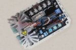
On the AVDR 054 the connection between A + C is the AC Voltage Sense Input and can be between 170 VAC to 520 VAC

the connection between B + C is the AC power supply and should be between 170VAC and 300VAC max

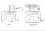
i left the B connection open in my wiring diagrams on purpose.

please check the AVDR 054 manual for connecting A, B and C to match your Genset setup for Voltage and Phases
The system as drawn will not provide VR functionality after excitation until B is connected as per AVDR Manual
Thank You
 

peapvp

Well-known member
Steel Soldiers Supporter
1,113
1,229
113
Location
Basehor, KS
Should the original vr box be disconnected? Both connectors?
Mike,

only the ADVR 053 can be connected to Chassis Ground for field flash.

Oshkosh had sold this ADVR 053 and this is where the idea came from to utilize a Pushbutton, diode and resistor to field flash.

my understanding is that ADVR 053 was discontinued and somehow people started to believe that the ADVR 054 is the sucessor of the ADVR 053, which is incorrect. These are two very different AVR’s

AVDR 053 Manual

AA08E5AD-B03D-4D06-AA0F-562DA993880C.jpeg
F892A4ED-710B-4607-8B01-649E8FD9BB43.jpeg
A209EC9D-6568-4C94-B7D9-D47080E3DEBC.jpeg
 
Last edited:

catienla

Member
52
43
18
Location
anawalt,wv
Thanks for the reply, I will start back on it this morning. I don't have a 24v relay here, will try to get one from Caterpillar tomorrow if i can. There aren't any supply houses close by have to order everything. I will get the voltage measurements you asked for. Thanks, again, Mike
 

jamawieb

Well-known member
1,437
556
113
Location
Ripley/TN
Years ago I wrote up my experience with converting a 005a with a advr-054. For the excitor I used a simple push button mounted next to the 24v breaker. I took 24v off the breaker over to the push button and then to F+. I put a 56ohm resistor (Dale CW-10) that is used in the 002-003a exciter board, then a 5406 diode. I also put the same diode coming from the VR to F+ because i was worried about current flowing from the push button to the VR and damaging it. All I have to do is start the unit as normal and the push the button in for 1 second to excite the field.
 

catienla

Member
52
43
18
Location
anawalt,wv
A to C .8 volts, F1to F2 .003vdc running with main contactor on, pushbutton pushed and released.
Not running 24vdc @ pushbutton 1.7 volt across F1-F2 with button down. I looked and don't have a 24v relay unless there is one in the old vr box.
 

catienla

Member
52
43
18
Location
anawalt,wv
Years ago I wrote up my experience with converting a 005a with a advr-054. For the excitor I used a simple push button mounted next to the 24v breaker. I took 24v off the breaker over to the push button and then to F+. I put a 56ohm resistor (Dale CW-10) that is used in the 002-003a exciter board, then a 5406 diode. I also put the same diode coming from the VR to F+ because i was worried about current flowing from the push button to the VR and damaging it. All I have to do is start the unit as normal and the push the button in for 1 second to excite the field.
24v to push button- push button to F+ or F1? Resistor and diode go where?
 

jamawieb

Well-known member
1,437
556
113
Location
Ripley/TN
A to C .8 volts, F1to F2 .003vdc running with main contactor on, pushbutton pushed and released.
Not running 24vdc @ pushbutton 1.7 volt across F1-F2 with button down. I looked and don't have a 24v relay unless there is one in the old vr box.
Can you take a picture of your VR setup? Also make sure the glass fuse is still good on the VR. Very 1st thing to do is make sure while your pressing the push button your getting voltage to F1 on the buss bar. If its getting DC power, it will produce some sort of voltage as long as the gen head is good. I agree with peapvp its not getting excited.
 

peapvp

Well-known member
Steel Soldiers Supporter
1,113
1,229
113
Location
Basehor, KS
Can you take a picture of your VR setup? Also make sure the glass fuse is still good on the VR. Very 1st thing to do is make sure while your pressing the push button your getting voltage to F1 on the buss bar. If its getting DC power, it will produce some sort of voltage as long as the gen head is good. I agree with peapvp its not getting excited.

Jamawieb, could you please post a wiring diagram of your setup? Do you ground the F2/F- to chassis so the exciter coil gets a proper connection for 24V?
 

catienla

Member
52
43
18
Location
anawalt,wv
resistor- Dale CW-5 56 ohm 5% 8815
diode- 1n5406 MIC
Circuit now goes 24vdc off circuit breaker on rear of control panel-momentary push button-button to resistor- resistor to diode- diode to F1 (grey stripe end)
F2 to chassis ground
When button pushed 24.9vdc on meter.
Nothing else in circuit.

Hooked A to L1 on main contactor (reconnection board side), B to L2 and C to L3, all dip switches off.
Have not started engine.
 

jamawieb

Well-known member
1,437
556
113
Location
Ripley/TN
This tread is about utilizing the existing S1 switch for excitation jamawiebb
The Pushbutton issue is discussed on catilena’s thread mep004 reads 0 phase to phase 480 phase to ground

thanks! Hope all is well
I could never get the jc-
resistor- Dale CW-5 56 ohm 5% 8815
diode- 1n5406 MIC
Circuit now goes 24vdc off circuit breaker on rear of control panel-momentary push button-button to resistor- resistor to diode- diode to F1 (grey stripe end)
F2 to chassis ground
When button pushed 24.9vdc on meter.
Nothing else in circuit.

Hooked A to L1 on main contactor (reconnection board side), B to L2 and C to L3, all dip switches off.
Have not started engine.
Looks like you have it correct. Did you check the glass fuse on the VR?
 

jamawieb

Well-known member
1,437
556
113
Location
Ripley/TN
Jamawieb, could you please post a wiring diagram of your setup? Do you ground the F2/F- to chassis so the exciter coil gets a proper connection for 24V?
From the 24v breaker to the monetary push button. From the push button to the resistor, after the resistor, the diode, then from the diode to F1 buss bar. I did put the exact same diode going from f+ on the vr to the buss bar F1 to make sure it wouldnt back feed and hurt the VR. F2 is connected to F- on the VR. Nothing else was done to F2. This has worked on 3phase 208v, 416v 3phase, and the single phase 240v conversion.
 

peapvp

Well-known member
Steel Soldiers Supporter
1,113
1,229
113
Location
Basehor, KS
From the 24v breaker to the monetary push button. From the push button to the resistor, after the resistor, the diode, then from the diode to F1 buss bar. I did put the exact same diode going from f+ on the vr to the buss bar F1 to make sure it wouldnt back feed and hurt the VR. F2 is connected to F- on the VR. Nothing else was done to F2. This has worked on 3phase 208v, 416v 3phase, and the single phase 240v conversion.
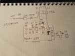
jamawieb, this would be the wiring diagram for your setup?

62620949-407E-40C9-8B63-29B9DF350E8F.jpeg
 

peapvp

Well-known member
Steel Soldiers Supporter
1,113
1,229
113
Location
Basehor, KS
Normally the excitation is done via R35 in special relay box
That creates a voltage between 3VDC to 6VDC on terminals F1/F2 with R being between 2 to 3 Ohm
 

peapvp

Well-known member
Steel Soldiers Supporter
1,113
1,229
113
Location
Basehor, KS
That will cause a AC Voltage between 50VAC to 100VAC on L1/L2 when generator is running - that’s excitation
 
Top
AdBlock Detected

We get it, advertisements are annoying!

Sure, ad-blocking software does a great job at blocking ads, but it also blocks useful features of our website like our supporting vendors. Their ads help keep Steel Soldiers going. Please consider disabling your ad blockers for the site. Thanks!

I've Disabled AdBlock
No Thanks