• Steel Soldiers now has a few new forums, read more about it at: New Munitions Forums!

  • Microsoft MSN, Live, Hotmail, Outlook email users may not be receiving emails. We are working to resolve this issue. Please add support@steelsoldiers.com to your trusted contacts.

My new 1992 M998 Avenger

springer1981

Well-known member
844
1,150
93
Location
Maine
I AM AMAZED I wish you were my neighbor! You are an engineer .....right?
LOL, thanks, no I am not an engineer. I'm just an enthusiast and my hobby is this truck. A little searching, reading, measuring and researching part numbers will get you a long way. I do have mechanical and electronic abilities but nothing more than most people could do if they applied themselves more.

And an FYI, all this and I don't have any idea if it will even work for what I want to do.
 

springer1981

Well-known member
844
1,150
93
Location
Maine
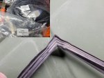
I purchased new X-door seals from MME ($30 each) and overall I am happy with the purchase however they are not exactly correct. They have the correct part numbers and they are labeled "replacement". There is a part number for each door. The description is front or rear and left or right. Since I only have front doors I naturally ordered a FR and a FL expecting molded exact fit seals.

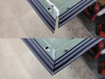
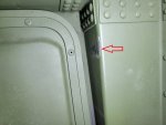
A picture of the labeled bags and a picture of the molded corner from the existing door seal below. I show the corner because this is what differentiates what seal goes where, right left etc. The rear are larger doors so the seals theoretically should be longer. Why this makes a difference is once I opened the bag and took the seal out it was nothing more than a straight piece of door seal. There was no molded corner and it was long enough to do any of the doors. I'm not sure why they go through the trouble to identify each one when they are all probably the same. I didn't buy rear door seals but you'll see what I mean.

door1.jpg
 
Last edited:

springer1981

Well-known member
844
1,150
93
Location
Maine
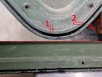
The first step was removing the old seal. The ends of the seal meet in the middle bottom of the door. I tried to pull it out but it's held in pretty tight so I started on the side and pulled out easy. I pulled the seal out of most of the door but the bottom and bottom corners were not budging. After a closer look I see that years of the doors being removed and set on the ground have bent in the edges and crimped the seal in. Using a wide screw driver I opened up the gap along the bottom edge enough to remove the rest of the seal. Then using the screw driver as gauge and backing I inserted it in the gap and used a hammer to make the channel uniform and straight again.

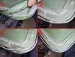
Number 1 in the picture below is the gap in the bottom corner. Number 2 is along the bottom and you can see it is narrower. This is after I opened up the gap to get the seal out of the corner. I fixed both corners. The bottom picture is along the bottom as well. You can see where the paint is chipped away is where I had to pry it open to get the seal out. This is also before I fixed it making it more uniform.
door2.jpg
 

springer1981

Well-known member
844
1,150
93
Location
Maine
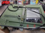
After the seal channel was fixed around the door it was time to put the new seal in. Since it is not molded with a corner I decided to make the corner the point where the seal ends would meet. Also this allowed me to feed the seal in. In the first picture there are 2 red arrows pointing to a piece of the door channel I removed. It is a small piece with only 2 rivets in it and removing it gave me easy access to feed the seal in. In that picture I have the seal worked about half way around the door. It gets progressively harder with each corner it goes around.

door3.jpg


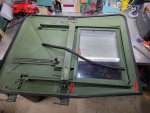
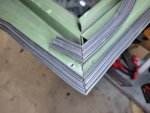
In this picture you can see the seal is now in place. It took about 30 minutes roughly. You can also see the left over piece I cut off. As I mentioned in a previous post, I believe this seal would fit any door, front or rear. The 2 Red Arrows point to the 2 rivets I removed.

door4.jpg


Here is a close up of the corner. I'll finish the corner with Cyanoacrylate glue (Krazy Glue). I didn't have the right rivets so I am holding off on completing the corner until I can rivet that piece back in. I also need to do the passenger side door but I can't open it enough to get the door off in my garage so I'll save that for another day.

door5.jpg
 

springer1981

Well-known member
844
1,150
93
Location
Maine
I changed the passenger side door seal today and it was more of a challenge so I took a couple pictures of the issue. I mentioned previously about the seal channel getting dented in and holding onto the seal making it difficult to remove. It's obvious these door have hit the ground a few times, probably like most of these doors.

It looks like it's common to hit the corners. You can see in picture 1 the metal trim with the channel for the door seal is crushed completely and it actually cut the seal. First I cut away the old seal, picture 2. Then I carefully used a screw driver to pry the channel apart until I could remove the old seal that was pinched in, picture 3. After the rubber was removed, I used the screw driver and a hammer to reshape the channel, picture 4.


door6.jpg


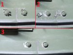
While removing the old seal I caught my knuckle on one of the rivets on the trim. When the doors were assembled the trim holes were never deburred as you can see in picture 1. I used a small screw driver with a good blade and sharp corners and a small hammer to chip away the burrs, picture 2. The results are in picture 3. Just needs a little touch up and the razor edges are gone.

door7.jpg
 

springer1981

Well-known member
844
1,150
93
Location
Maine
Today I finished the door seals. I used Krazy Glue to make the corner and it worked great. First I did a test piece to see how long it took to setup and how well it holds. I was happy with the results and did the corners. The black that looks it's messed up is just the glue, the picture does not do it justice.

door8.jpg


The old seal rubbed on the door jam at the top as well as folded out at the bottom. The goal was to fix that. When I put the door back on it still rubbed so I needed to adjust the door. It was already all the way forward and that seems to be what caused the problem in the first place. I ended up elongating the holes in the door to adjust the hinges more and that solved all the problems. New seal, door adjusted and they work like new.

door9.jpg
 

springer1981

Well-known member
844
1,150
93
Location
Maine
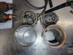
I took the parts motor for the turret drive apart today. The part I wanted is the motor body with the magnets in it. The motor suffered the fate as the turret motor, rusted inside. The bearings were seized, lots of corrosion and rust, though not as much as the turret motor. The motor on the right is the parts motor. You can see the magnets inside are intact and that was the most important part.

m3.jpg


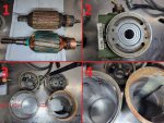
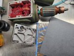
In picture one you can see the armature on the bottom is the one I need to use. It cleaned up nicely and it ready to go. Picture 2 is a new bearing and seal installed in the gear box. Picture 3, same picture as above shows the motor body comparison. The one from the turret on the left is machined for an o-ring seal and the motor end caps/bearing supports. The parts one on the right is not machined for o-rings or the end caps I need to use. Close up in picture 4.

m4.jpg
 

springer1981

Well-known member
844
1,150
93
Location
Maine
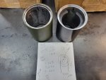
So I took the 2 motor bodies to my shop and measured them. The parts body was about 1/8" longer and slightly smaller diameter. I'm guessing the dimensions for that motor are metric. I chucked up the body in a lathe and cut to the same length. Then turned the ends for the o-rings and end caps. Should fit everything now but still waiting on a bearing before I can reassemble it. You can see the sharpie marks inside the old body where I was estimating the magnet locations. This was important to sizing up the length so the magnets would be in the same approximate location.

m5.jpg
 
Last edited:

springer1981

Well-known member
844
1,150
93
Location
Maine
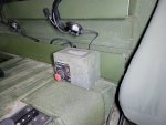
I took apart the turret controller (BPMTU) and started rewiring it. Removed some of the bulky mounts and connectors I won't be using. I will be remounting the power and joystick connectors on top. It sits beside the driver seat and conveniently if I reach over and back my hand goes right to the power/stop button.


Controller.jpg
 

springer1981

Well-known member
844
1,150
93
Location
Maine
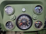
After the 4L80 upgrade I still needed to upgrade the speedometer. I had one with a couple small dents in the bezel and was fixing it and the plan was to paint if green to match the rest of the gauges however I came across one in like new condition. I finished mounting and wiring it and was able to keep the original finish.

sp1.jpg


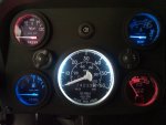
The gauge lighting is different than the original 60mph gauge in that it has it's own bulb. The original gauges use a back lighting rather than individual lighting. The new speedo is much different and I have to work on how to make it a nice crisp white light rather than the dull orangish color it is now.

Here is Old vs New

sp3.jpg

sp2.jpg
 
  • Like
Reactions: OBX

Coug

Well-known member
Steel Soldiers Supporter
3,003
4,420
113
Location
Olympia/WA
the dull orangish light is probably better on the eyes when driving at night. The bright white is kind of harsh on the eyes, especially when trying to switch between dark outside and bright gauges.
 

springer1981

Well-known member
844
1,150
93
Location
Maine
the dull orangish light is probably better on the eyes when driving at night. The bright white is kind of harsh on the eyes, especially when trying to switch between dark outside and bright gauges.
I thought that too but honestly I can see the speedo much better and the light didn't bother me at all. Not as bright as the picture makes it seem.


I am trying to figure out why the little gauges are different colors.
I doubt I am ever speeding at night, so I don't need to see mine that bad.
Just a Patriotic Red, White and Blue color scheme and to be a little different.
 

springer1981

Well-known member
844
1,150
93
Location
Maine
I started reassembling the turret drive. Filled the gearbox with grease which is what i think is what I took out however what I took out seemed to have broken down. The gasket for the top of the gearbox was damaged when I removed it and I had to make one. I guess making your own gaskets is a lost art these days. I had to go to 3 auto parts stores before I found a mixed pack of gasket material. The first store didn't even know you could make your own gaskets! The second one had 1 kind of gasket paper for making your own water pump gasket. The last one, the guy wanted to know what it was for so he could look up the part number. I told him it was machine gun turret drive cover gasket for a Humvee. That pretty much put an end to the questions. He then took me out back to show me the gasket material. It was high up on a stock shelf and he handed me everything but the mixed pack. Then he said and we have this too. I was dumb founded by the whole experience.

gasket.jpg


Then I proceeded to make a new gasket. As a kid/young adult I think I bought a mix pack of gasket material every other weekend to make some sort of gasket.

gasket2.jpg


After the top was sealed I started fitting the motor parts. The new body fit perfectly and the magnets are in the correct place. You can tell if the magnets are in the correct location because the armature will come to a rest in the magnetic field and if the ends and bearings line up it is correct. If you have to force the armature in either direction to fit an end cap then the magnets are not in the correct location.

I cleaned the brushes and brush holders and it all looks good. I do need to extend the power cable so I wasn't able to finish assembly today.

gasket3.jpg
 

Mullaney

Well-known member
Steel Soldiers Supporter
Supporting Vendor
7,774
19,893
113
Location
Charlotte NC
I started reassembling the turret drive. Filled the gearbox with grease which is what i think is what I took out however what I took out seemed to have broken down. The gasket for the top of the gearbox was damaged when I removed it and I had to make one. I guess making your own gaskets is a lost art these days. I had to go to 3 auto parts stores before I found a mixed pack of gasket material. The first store didn't even know you could make your own gaskets! The second one had 1 kind of gasket paper for making your own water pump gasket. The last one, the guy wanted to know what it was for so he could look up the part number. I told him it was machine gun turret drive cover gasket for a Humvee. That pretty much put an end to the questions. He then took me out back to show me the gasket material. It was high up on a stock shelf and he handed me everything but the mixed pack. Then he said and we have this too. I was dumb founded by the whole experience.

View attachment 860789


Then I proceeded to make a new gasket. As a kid/young adult I think I bought a mix pack of gasket material every other weekend to make some sort of gasket.

View attachment 860790


After the top was sealed I started fitting the motor parts. The new body fit perfectly and the magnets are in the correct place. You can tell if the magnets are in the correct location because the armature will come to a rest in the magnetic field and if the ends and bearings line up it is correct. If you have to force the armature in either direction to fit an end cap then the magnets are not in the correct location.

I cleaned the brushes and brush holders and it all looks good. I do need to extend the power cable so I wasn't able to finish assembly today.

View attachment 860797
.
Sadly - without something to type into their computer - the so called "parts counter" people these days are pretty useless...

.
 

springer1981

Well-known member
844
1,150
93
Location
Maine
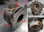
The motor has a holding brake that was corroded and rusty as well as frozen. I took it all apart to see if I could clean it up and get it working. You can see the condition in the pictures on the right side. I had to drill out small allen screws holding it together, those are the heads in the top right picture.

Here's the theory of operation. #1 is the mounting plate that holds it to the end cap of the motor (see bottom right picture). #2 points to a plastic brake disc with a hex in the center (see upper right picture). At the end of the armature there is a matching hex that engages the brake disc. #3 is the brake body that contains a coil to make an electromagnet. Between #3 and #4 are 6 springs that apply pressure on the plastic brake disc by pressing it against #1. When the coil is energized and the magnet is on, #4 is pulled toward the brake body releasing the pressure from the brake disc. At the same time the brake is released power is applied to the motor making it spin. When power to the motor is stopped, power is also removed from the coil causing the springs to put pressure on #4 and holding the motor in place.

After I took it all apart, cleaned everything and reassembled it I couldn't for the life of me figure out how it could possible work. The plastic brake disc was rusted solid to #4, so much so that I thought it was suppose to be attached (can be seen in upper right picture). Finally I decided it must be 2 separate parts and pried them apart, you would have thought they were bonded together. Cleaned it up, reassembled and tested it. It Works!!

brake.jpg
 

springer1981

Well-known member
844
1,150
93
Location
Maine
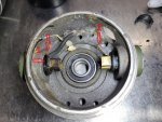
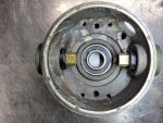
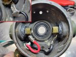
The Brush end cap had a unique problem. The power wires were crimped to the brush holders, #1 in the picture. There was no way I could save crimp and reuse it. I didn't want to splice the wires in the end cap and soldering isn't acceptable in a high current draw like this. So I started looking at the parts motor to see if there was a way I could use those brush holders. After a lot of measuring I decided to give it a shot. The parts brush holders use a spade terminal connection, #2 in the picture. The wire gets a crimped on terminal end and then the spade terminal is soldered on after it is connected so it can't come apart.

The brushes for the parts motor were in better shape, less use and the holders were not oxidized. It's a "no turning back" move to remove the brush holders so I started with the parts motor first and managed to get them out in one piece. Then I had to destructively remove them from the good end cap. I then had to open the hole in the end cap until the new brush holders were a press fit. I did the first one so I could use the old one to line it up straight. Then did the second one using the newly installed one to line it up. After they were both installed I used some good ole JB Weld around the insulator to ensure it stays put. The original holders had an epoxy holding them in also.

brushes.jpg


Here's the end result with new brush holders installed.

brushes2.jpg
 

springer1981

Well-known member
844
1,150
93
Location
Maine
I ordered a couple LED lights that matched the ones I used on the dash panel. The new speedometer had an incandescent light bulb that I figured was the reason the lighting is orangish.


I changed out the light bulb and here's the results. I also changed out the Tachometer light as well. It is not nearly as bright as it seems in the photo.

sp4.jpg
 

springer1981

Well-known member
844
1,150
93
Location
Maine
The original wire used for the motor was a 4 conductor multi gauge wire. Two 12 gauge wires and two 14 gauge wires. I wasn't able to find that wire so I went with 12/4 outdoor audio cable. Any other 12/4 wire was too thick to fit the water tight compression fitting. I crimped on spade terminals and connected them and then soldered the terminal in place (upper left close up) to prevent it from ever coming free.


motor4.jpg


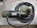
With the wire connected it was finally time to put the motor together. Since the motor is going to be used (hopefully) for the rear steering and mounted in the rear, I have about 20' of wire attached.

motor5.jpg


And of course .... The TEST

 
Top
AdBlock Detected

We get it, advertisements are annoying!

Sure, ad-blocking software does a great job at blocking ads, but it also blocks useful features of our website like our supporting vendors. Their ads help keep Steel Soldiers going. Please consider disabling your ad blockers for the site. Thanks!

I've Disabled AdBlock
No Thanks