tim292stro
Well-known member
- 2,118
- 41
- 48
- Location
- S.F. Bay Area/California
I see. When saying Plan B, I immediately thought of Plan B Supply... not the same thing.  . I had never heard of that, and had I known about it I would have steered them in a different direction.
So the DUVAC system (marketing name) was a Leece Neville product for remote sensing a battery voltage beyond a battery isolator - it's really just that simple despite what marketing people will tell you.
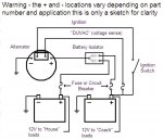
The voltage regulator from any remote sensing alternator should work for this setup. Models that have this that comes to mind are the Delco 24SI and 28SI, which is available in a Bosch sized (TINY!!) case and 100Amps out at 24V (higher at 12V, they have a 200Amp 12V model). They even have a remote sense bulletin for the remote sense across an isolator for replacing the DUVAC Leece Neville setup - be aware that the "Special Isolator" they are talking about is a relay with a current limiting regulator back feeding the alternator from the chassis battery when the ignition is on. Any cheap isolator diode and be made to work with other cheap parts that make this happen.
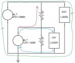
Your 24Volt system is the green loop, your 12V system is the blue loop. What your 12V battery and alternator can't do is reverse feed the upper 12V battery (red arrow) - think of it this way, any volts you add in the correct polarity are subtracted by the reverse polarity of the upper battery (+12) + (-12) = 0. There is no current flow on the red path, so your 24 volt loads only see the power generated by the 24V alternator (green path), and your 12V loads only see the power generated by the 12V alternator (blue path). The problem here is that the 24V alternator is also trying to charge the series string of batteries, so if you turn on a 12V load, the 24V alternator sees the total system voltage drop, and increases its output to compensate. The lower 12V alternator does the same thing, so the 24V alternator sees a higher system voltage and cuts its field to compensate. Basically your alternators end up in a tug of war because of your 12V loads.
Looking at how Chevy did the rest of the CUCVs and how Recovry4x4 did "his" Plan B 2.0 (really the same thing GM did...):
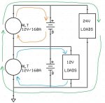
You can see the difference in voltage/power flow - the 24V loads see both alternators (green path) in series just like the batteries, the 12V loads only see the lower 12V alternator and battery (blue path), and the upper battery gets just the voltage it likes based on the isolated ground upper 12V alternator (orange path). What this means though is you have 160A of 12V OR 160A of 24V max. The reason this distinction is important is that the lower 12V alternator has to split its duty between 12V loads and 24V loads. The 24V charging system can only supply what's left of the lower alternator after the demands of the 12V system - meaning if you had 60Amps of 12V drawn from the lower alternator, the 24V system would only be able to generate 100Amps of 24V. For the pickup and blazer version of the CUCV where the only 24V loads were the glow plugs starter and radio, all intermittent demand loads, this allowed a lot of down time to charge/run the 12V half of the system (lights, wipers, heater). You can account for this by installing a larger alternator for the lower 12V side of the system - the military chose part number simplicity and just made both as large as they forecasted the lower would need to be, you could do the same thing and put in dual 210Amp 12V isolated alternators. You can also reduce the 12V loads in your chassis system by using LEDs where possible, and 24V devices for the larger loads (this may require adding other complexity like 12V relays to control the 24V loads from the original control systems).
Where a Vanner helps out normally is in transit applications where you'd have a 24V alternator and a huge heater or A/C with 24V motors that suck 50+Amps each, and 24V interior lights, but then you also have standard 12V exterior lights and controls. In that case, they also don't want to add an alternator into what is usually an already crowded engine compartment, so you add a Vanner to the battery compartment:
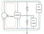
As you would expect, the 24V loads see the 24V alternator (green path), but the 12V loads see the Vanner (blue path). For charging the 12V lower battery and supplying the 12V loads, the Vanner appears as a 24V load to the 24V system (orange path).
What I was proposing was the other way you can use a Vanner, which is to charge a separate 12V bank from a 24V supply. You can see how this might work by looking at the above diagram's orange and blue traces, basically you add that on to the existing system when you're ready:

Here the house bank get charged via the 24V red path, and the house loads see their own isolated 12V blue path. The chassis 24V and 12V circuits are for all intents and purposes unmodified from the stock CUCV setup, and eliminates the DUVAC system completely. 200+Amp MRAP alternators are available for dirt cheap, and are very easy to find right now. I picked up three 450A alternators from a seller here on SS for $150 each a while back...
Hopefully I haven't confused you, and I've shown there are many ways to skin a pig, no one right way is more right - but the Plan B system should IMHO probably be put on a shelf in favor of a correctly designed Plan A system for the sake of reliability...![Thumbs Up [thumbzup] [thumbzup]](https://www.steelsoldiers.com/images/smilies/icon_smile_thumzup.gif)
So the DUVAC system (marketing name) was a Leece Neville product for remote sensing a battery voltage beyond a battery isolator - it's really just that simple despite what marketing people will tell you.

The voltage regulator from any remote sensing alternator should work for this setup. Models that have this that comes to mind are the Delco 24SI and 28SI, which is available in a Bosch sized (TINY!!) case and 100Amps out at 24V (higher at 12V, they have a 200Amp 12V model). They even have a remote sense bulletin for the remote sense across an isolator for replacing the DUVAC Leece Neville setup - be aware that the "Special Isolator" they are talking about is a relay with a current limiting regulator back feeding the alternator from the chassis battery when the ignition is on. Any cheap isolator diode and be made to work with other cheap parts that make this happen.
This would be correct.This sounds like a very clean solution. The only down side is fewer amps of 24V power. If I'm right in assuming you're using the 160A 12V alts, that gives you 160A of 24V available from the alternators...
This would be incorrect. If you have a 200Amp 24V alternator, then you have 200Amps of 24V. The 160Amp alternator your have on your lower 12V battery in the series string can only charge the 12V battery and supply 12V loads, it cannot send power to the upper 12V battery and the 24Volt loads attached to it. You have to think of electrical systems in terms of loops:...The original Plan B mod gives you 280A of 24V power from the alternators, if I understand correctly...

Your 24Volt system is the green loop, your 12V system is the blue loop. What your 12V battery and alternator can't do is reverse feed the upper 12V battery (red arrow) - think of it this way, any volts you add in the correct polarity are subtracted by the reverse polarity of the upper battery (+12) + (-12) = 0. There is no current flow on the red path, so your 24 volt loads only see the power generated by the 24V alternator (green path), and your 12V loads only see the power generated by the 12V alternator (blue path). The problem here is that the 24V alternator is also trying to charge the series string of batteries, so if you turn on a 12V load, the 24V alternator sees the total system voltage drop, and increases its output to compensate. The lower 12V alternator does the same thing, so the 24V alternator sees a higher system voltage and cuts its field to compensate. Basically your alternators end up in a tug of war because of your 12V loads.
Looking at how Chevy did the rest of the CUCVs and how Recovry4x4 did "his" Plan B 2.0 (really the same thing GM did...):

You can see the difference in voltage/power flow - the 24V loads see both alternators (green path) in series just like the batteries, the 12V loads only see the lower 12V alternator and battery (blue path), and the upper battery gets just the voltage it likes based on the isolated ground upper 12V alternator (orange path). What this means though is you have 160A of 12V OR 160A of 24V max. The reason this distinction is important is that the lower 12V alternator has to split its duty between 12V loads and 24V loads. The 24V charging system can only supply what's left of the lower alternator after the demands of the 12V system - meaning if you had 60Amps of 12V drawn from the lower alternator, the 24V system would only be able to generate 100Amps of 24V. For the pickup and blazer version of the CUCV where the only 24V loads were the glow plugs starter and radio, all intermittent demand loads, this allowed a lot of down time to charge/run the 12V half of the system (lights, wipers, heater). You can account for this by installing a larger alternator for the lower 12V side of the system - the military chose part number simplicity and just made both as large as they forecasted the lower would need to be, you could do the same thing and put in dual 210Amp 12V isolated alternators. You can also reduce the 12V loads in your chassis system by using LEDs where possible, and 24V devices for the larger loads (this may require adding other complexity like 12V relays to control the 24V loads from the original control systems).
Where a Vanner helps out normally is in transit applications where you'd have a 24V alternator and a huge heater or A/C with 24V motors that suck 50+Amps each, and 24V interior lights, but then you also have standard 12V exterior lights and controls. In that case, they also don't want to add an alternator into what is usually an already crowded engine compartment, so you add a Vanner to the battery compartment:

As you would expect, the 24V loads see the 24V alternator (green path), but the 12V loads see the Vanner (blue path). For charging the 12V lower battery and supplying the 12V loads, the Vanner appears as a 24V load to the 24V system (orange path).
What I was proposing was the other way you can use a Vanner, which is to charge a separate 12V bank from a 24V supply. You can see how this might work by looking at the above diagram's orange and blue traces, basically you add that on to the existing system when you're ready:

Here the house bank get charged via the 24V red path, and the house loads see their own isolated 12V blue path. The chassis 24V and 12V circuits are for all intents and purposes unmodified from the stock CUCV setup, and eliminates the DUVAC system completely. 200+Amp MRAP alternators are available for dirt cheap, and are very easy to find right now. I picked up three 450A alternators from a seller here on SS for $150 each a while back...
Hopefully I haven't confused you, and I've shown there are many ways to skin a pig, no one right way is more right - but the Plan B system should IMHO probably be put on a shelf in favor of a correctly designed Plan A system for the sake of reliability...
Last edited:


 <--24V Alt [/EDIT]