• Steel Soldiers now has a few new forums, read more about it at: New Munitions Forums!

  • Microsoft MSN, Live, Hotmail, Outlook email users may not be receiving emails. We are working to resolve this issue. Please add support@steelsoldiers.com to your trusted contacts.

M1010 for my daughter the field biologist

tim292stro

Well-known member
2,118
41
48
Location
S.F. Bay Area/California
I see. When saying Plan B, I immediately thought of Plan B Supply... not the same thing. :). I had never heard of that, and had I known about it I would have steered them in a different direction.

So the DUVAC system (marketing name) was a Leece Neville product for remote sensing a battery voltage beyond a battery isolator - it's really just that simple despite what marketing people will tell you.
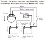
DUVAC.jpg

The voltage regulator from any remote sensing alternator should work for this setup. Models that have this that comes to mind are the Delco 24SI and 28SI, which is available in a Bosch sized (TINY!!) case and 100Amps out at 24V (higher at 12V, they have a 200Amp 12V model). They even have a remote sense bulletin for the remote sense across an isolator for replacing the DUVAC Leece Neville setup - be aware that the "Special Isolator" they are talking about is a relay with a current limiting regulator back feeding the alternator from the chassis battery when the ignition is on. Any cheap isolator diode and be made to work with other cheap parts that make this happen.
This sounds like a very clean solution. The only down side is fewer amps of 24V power. If I'm right in assuming you're using the 160A 12V alts, that gives you 160A of 24V available from the alternators...
This would be correct.

...The original Plan B mod gives you 280A of 24V power from the alternators, if I understand correctly...
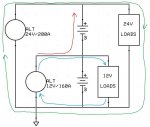
This would be incorrect. If you have a 200Amp 24V alternator, then you have 200Amps of 24V. The 160Amp alternator your have on your lower 12V battery in the series string can only charge the 12V battery and supply 12V loads, it cannot send power to the upper 12V battery and the 24Volt loads attached to it. You have to think of electrical systems in terms of loops:
12v24v-dual_alt.jpg

Your 24Volt system is the green loop, your 12V system is the blue loop. What your 12V battery and alternator can't do is reverse feed the upper 12V battery (red arrow) - think of it this way, any volts you add in the correct polarity are subtracted by the reverse polarity of the upper battery (+12) + (-12) = 0. There is no current flow on the red path, so your 24 volt loads only see the power generated by the 24V alternator (green path), and your 12V loads only see the power generated by the 12V alternator (blue path). The problem here is that the 24V alternator is also trying to charge the series string of batteries, so if you turn on a 12V load, the 24V alternator sees the total system voltage drop, and increases its output to compensate. The lower 12V alternator does the same thing, so the 24V alternator sees a higher system voltage and cuts its field to compensate. Basically your alternators end up in a tug of war because of your 12V loads.

Looking at how Chevy did the rest of the CUCVs and how Recovry4x4 did "his" Plan B 2.0 (really the same thing GM did...):
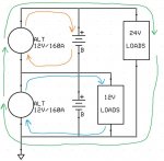
12v12v-dual_alt.jpg

You can see the difference in voltage/power flow - the 24V loads see both alternators (green path) in series just like the batteries, the 12V loads only see the lower 12V alternator and battery (blue path), and the upper battery gets just the voltage it likes based on the isolated ground upper 12V alternator (orange path). What this means though is you have 160A of 12V OR 160A of 24V max. The reason this distinction is important is that the lower 12V alternator has to split its duty between 12V loads and 24V loads. The 24V charging system can only supply what's left of the lower alternator after the demands of the 12V system - meaning if you had 60Amps of 12V drawn from the lower alternator, the 24V system would only be able to generate 100Amps of 24V. For the pickup and blazer version of the CUCV where the only 24V loads were the glow plugs starter and radio, all intermittent demand loads, this allowed a lot of down time to charge/run the 12V half of the system (lights, wipers, heater). You can account for this by installing a larger alternator for the lower 12V side of the system - the military chose part number simplicity and just made both as large as they forecasted the lower would need to be, you could do the same thing and put in dual 210Amp 12V isolated alternators. You can also reduce the 12V loads in your chassis system by using LEDs where possible, and 24V devices for the larger loads (this may require adding other complexity like 12V relays to control the 24V loads from the original control systems).

Where a Vanner helps out normally is in transit applications where you'd have a 24V alternator and a huge heater or A/C with 24V motors that suck 50+Amps each, and 24V interior lights, but then you also have standard 12V exterior lights and controls. In that case, they also don't want to add an alternator into what is usually an already crowded engine compartment, so you add a Vanner to the battery compartment:
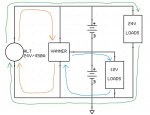
24V-single_alt.jpg

As you would expect, the 24V loads see the 24V alternator (green path), but the 12V loads see the Vanner (blue path). For charging the 12V lower battery and supplying the 12V loads, the Vanner appears as a 24V load to the 24V system (orange path).


What I was proposing was the other way you can use a Vanner, which is to charge a separate 12V bank from a 24V supply. You can see how this might work by looking at the above diagram's orange and blue traces, basically you add that on to the existing system when you're ready:
Chassis-House.jpg
Here the house bank get charged via the 24V red path, and the house loads see their own isolated 12V blue path. The chassis 24V and 12V circuits are for all intents and purposes unmodified from the stock CUCV setup, and eliminates the DUVAC system completely. 200+Amp MRAP alternators are available for dirt cheap, and are very easy to find right now. I picked up three 450A alternators from a seller here on SS for $150 each a while back...


Hopefully I haven't confused you, and I've shown there are many ways to skin a pig, no one right way is more right - but the Plan B system should IMHO probably be put on a shelf in favor of a correctly designed Plan A system for the sake of reliability... [thumbzup]
 
Last edited:

jpg

Member
611
15
18
Location
Boston, MA
Wow. Thanks! I was hoping someone with expertise in this area would chime in. It will take me a little time to digest this. I do have one point of confusion that i can articulate. why is it that the lower alt can contribute amps when the alts are wired in series, but not when "nested" as in the plan b mod?

thanks,
-jpg

I see. When saying Plan B, I immediately thought of Plan B Supply... not the same thing. :). I had never heard of that, and had I known about it I would have steered them in a different direction.

So the DUVAC system (marketing name) was a Leece Neville product for remote sensing a battery voltage beyond a battery isolator - it's really just that simple despite what marketing people will tell you.
View attachment 580566

The voltage regulator from any remote sensing alternator should work for this setup. Models that have this that comes to mind are the Delco 24SI and 28SI, which is available in a Bosch sized (TINY!!) case and 100Amps out at 24V (higher at 12V, they have a 200Amp 12V model). They even have a remote sense bulletin for the remote sense across an isolator for replacing the DUVAC Leece Neville setup - be aware that the "Special Isolator" they are talking about is a relay with a current limiting regulator back feeding the alternator from the chassis battery when the ignition is on. Any cheap isolator diode and be made to work with other cheap parts that make this happen.


This would be correct.


This would be incorrect. If you have a 200Amp 24V alternator, then you have 200Amps of 24V. The 160Amp alternator your have on your lower 12V battery in the series string can only charge the 12V battery and supply 12V loads, it cannot send power to the upper 12V battery and the 24Volt loads attached to it. You have to think of electrical systems in terms of loops:
View attachment 580571

Your 24Volt system is the green loop, your 12V system is the blue loop. What your 12V battery and alternator can't do is reverse feed the upper 12V battery (red arrow) - think of it this way, any volts you add in the correct polarity are subtracted by the reverse polarity of the upper battery (+12) + (-12) = 0. There is no current flow on the red path, so your 24 volt loads only see the power generated by the 24V alternator (green path), and your 12V loads only see the power generated by the 12V alternator (blue path). The problem here is that the 24V alternator is also trying to charge the series string of batteries, so if you turn on a 12V load, the 24V alternator sees the total system voltage drop, and increases its output to compensate. The lower 12V alternator does the same thing, so the 24V alternator sees a higher system voltage and cuts its field to compensate. Basically your alternators end up in a tug of war because of your 12V loads.

Looking at how Chevy did the rest of the CUCVs and how Recovry4x4 did "his" Plan B 2.0 (really the same thing GM did...):
View attachment 580575

You can see the difference in voltage/power flow - the 24V loads see both alternators (green path) in series just like the batteries, the 12V loads only see the lower 12V alternator and battery (blue path), and the upper battery gets just the voltage it likes based on the isolated ground upper 12V alternator (orange path). What this means though is you have 160A of 12V OR 160A of 24V max. The reason this distinction is important is that the lower 12V alternator has to split its duty between 12V loads and 24V loads. The 24V charging system can only supply what's left of the lower alternator after the demands of the 12V system - meaning if you had 60Amps of 12V drawn from the lower alternator, the 24V system would only be able to generate 100Amps of 24V. For the pickup and blazer version of the CUCV where the only 24V loads were the glow plugs starter and radio, all intermittent demand loads, this allowed a lot of down time to charge/run the 12V half of the system (lights, wipers, heater). You can account for this by installing a larger alternator for the lower 12V side of the system - the military chose part number simplicity and just made bath as large as they forecasted the lower would need to be, you could do the same thing and put in dual 210Amp 12V isolated alternators. You can also reduce the 12V loads in your chassis system by using LEDs where possible, and 24V devices for the larger loads (this may require adding other complexity like 12V relays to control the 24V loads from the original control systems).

Where a Vanner helps out normally is in transit applications where you'd have a 24V alternator and a huge heater or A/C with 24V motors that suck 50+Amps each, and 24V interior lights, but then you also have standard 12V exterior lights and controls. In that case, they also don't want to add an alternator into what is usually an already crowded engine compartment, so you add a Vanner to the battery compartment:
View attachment 580578

As you would expect, the 24V loads see the 24V alternator (green path), but the 12V loads see the Vanner (blue path). For charging the 12V lower battery and supplying the 12V loads, the Vanner appears as a 24V load to the 24V system (orange path).


What I was proposing was the other way you can use a Vanner, which is to charge a separate 12V bank from a 24V supply. You can see how this might work by looking at the above diagram's orange and blue traces, basically you add that on to the existing system when you're ready:
View attachment 580579
Here the house bank get charged via the 24V red path, and the house loads see their own isolated 12V blue path. The chassis 24V and 12V circuits are for all intents and purposes unmodified from the stock CUCV setup, and eliminates the DUVAC system completely. 200+Amp MRAP alternators are available for dirt cheap, and are very easy to find right now. I picked up three 475A alternators from a seller here on SS for $150 each a while back...


Hopefully I haven't confused you, and I've shown there are many ways to skin a pig, no one right way is more right - but the Plan B system should IMHO probably be put on a shelf in favor of a correctly designed Plan A system for the sake of reliability... [thumbzup]
 

tim292stro

Well-known member
2,118
41
48
Location
S.F. Bay Area/California
Again, it comes down to how the voltage regulators in the alternators are designed. Their "world view" is that they are the ONLY contributor of power generation to an electrical system. The voltage regulator manages the voltage of the alternator by controlling the current of the field coil in a small regulation window. Regulators already have a complicated set of algorithms inside to handle things like temperature differences, load dumps (don't want the alternator to run away to 16V on a 12V system or 32V on a 24V system). Typically the dump event is a "holy cow" moment and the alternator cuts the field rapidly, when the voltage is too low, the regulator assumes the load can run from the battery while it slowly walks in the voltage - so here you have two sides of the control, one is fast (cut) and one is really slow (ramp up). The regulation window is also very small +/-0.25V typically, that is the area from the highest output (-0.25 low) to the field being turned off (+0.25V).

So here's where having two dynamic controls operating the same system gets messy, if the higher power alternator ramps faster than the lower power alternator would, the lower power alternator would see the voltage outside its regulation window and cut the field (no power generation). This would draw the battery down until it's below the regulation window at which point it ramps up. This causes the other alternator to see a higher system voltage and cut its field. Kind of like a game of ping pong, but it has the wear and tear of playing ping pong with wrecking balls... auaaua (<--- if only I could turn one of these guys around so they were banging their heads on the same wall it would have the effect I'm looking for [thumbzup])

Your alternators will be constantly turning on and off, and your batteries will be seeing very short charges and discharges of basically full load, which is the worst thing you can do to an automotive electrical system for reliability.


[EDIT:] It occurred to me on my drive into work there was another analogy that people might relate to for dual "nested" alternators vs single alternators: The world economy. It would be very simple if there was only one country, and that one country made all of the economic rules for the whole planet. In this setup there is one person in control of everything and there is no one to have a conflict with. Make it US vs Russia, or US vs China, and most people would agree that some complication comes into play. Both the US and the other country want to make and use things for everyone, and they both want to be in complete control. The only way it works is with cooperation, to be sure there is some conflict, but there are diplomatic ways to resolve those problems before they get into all out war. Your simple alternator and voltage regulator is designed for the "one country world", throw in another country without arranging some form of electronic cooperation (the "diplomats" would be a current sharing control circuit in each regulator and a modified regulation algorithm to take into account of what the other alternator is doing) and you have mine vs yours wars... And like in war it's usually whoever can do the most damage to the other person who wins: 12V Alt-->:burn:<--24V Alt [/EDIT]


What a Vanner does is different, it's "world view" is that one output (12V) should be exactly half of what its input is (24V) - it's just that simple. If there are loads on the 12V tap that are greater than the total 24V system, it "fights" that imbalance by sending more current at the 1/2-input voltage. This keeps the batteries equally charged, and the 12V loads supplied. As far as the 24V alternator is concerned it only sees a 24V system, so its world view doesn't get affected.

[EDIT:] Using the world economy analogy for a Vanner setup, the main country (24V system) is the one who makes and uses the most baseballs. A small island state like say Hawaii (Vanner) which is part of the country buys baseballs from the mainland in 24 packs. When the ship arrives, they open the packages and split the boxes into two 12 packs or half (12V) and ship them to New Zealand without telling the mainland. As far as the mainland is concerned Hawaii uses what it makes. New Zealand gets the smaller packages they prefer. Everyone is happy and no one is the wiser. [thumbzup] [/EDIT]


That said, you can "team" multiple parallel alternators of the voltage/current same rating, you'd need to use an external regulator for that though. I don't recommend it without sound understanding of electricity - it would also be harder to have a general mechanic troubleshoot it.

Alternators that are dual voltage actually have a Vanner-type device in the regulator box (and are more expensive for that reason).
 
Last edited:

Recovry4x4

LLM/Member 785
Super Moderator
Steel Soldiers Supporter
34,012
1,810
113
Location
GA Mountains
This sounds like a very clean solution. The only down side is fewer amps of 24V power. If I'm right in assuming you're using the 160A 12V alts, that gives you 160A of 24V available from the alternators. The original Plan B mod gives you 280A of 24V power from the alternators, if I understand correctly. Most folks won't notice the 120A difference, unless they run a big 24V inverter or winch, or other large 24V load.
Yes, some amperage was lost which isn't a factor for me. The advantage is that now both of my alts are readily available at any over the road truck parts house.
 

jpg

Member
611
15
18
Location
Boston, MA
OK. I understand the previous messages now.

What should I do now? I have a 24v inverter and a 24v winch that draws a max of 275 amps at 7% duty cycle, so I hate to lose 24v amps if I don't have to. IIUC, I either replace my 24v alternator with a 12v and run them independantly in series, or I replace my 12v alternator with a 24v and run them in parallel with a voltage regulator that coordinates them, and something like a vanner to supply 12v. are there other better options?
 

tim292stro

Well-known member
2,118
41
48
Location
S.F. Bay Area/California
Probably the simplest is to size the batteries and inverter for the loads and get the biggest 24V alternator you can manage in there.

The winch is probably going to run while the engine is going to run, the inverter is more likely to run while the truck is off. Right? Separate those two running scenarios in your mind first.


  1. While running the alternator and batteries need to support the load of the winch for 7% of the time, and the alternator needs to be able to replenish what the batteries lost to the winch within that remaining 93% of time. (275 Max for 7 seconds means you'd have to wait 93 seconds before using the winch again, and you'd need to recharge your battery with a 200A alternator for about ((1.25x275)/200)x7 = ~12 seconds recharge. You have plenty of Alternator for that load if you ensure the deficit of (200 - 275 =) -75Amps doesn't drain your batteries while you are in the process of winching.
  2. Only the batteries need to support the inverter (engine stopped, no alternator contribution) for the expected load and run time, the alternator needs to only meet the charging needs of the batteries in the amount of time you expect to run the truck before the next time you use the inverter.

These two categories are to separate the running ratings of everything. You can still power both of these loads form the same alternator(s) and battery bank as long as you design for the maximum need in either situation.


That said, my personal preference would be to accommodate these loads by splitting the two loads into separate systems by having two banks charged by their own alternator. One bank being the "chassis+winch", the other the "house/inverter". We like our toys and comforts, so it's more likely we will misuse the house system by leaving a light on when we fall asleep, or leaving the inverter turned on while there is no load running on it forgetting that it still sucks down the battery with no load... Nothing ruins a trip like leaving your warm comfortable RV to go find a tow truck in the rain or snow :roll:.

If you want to retain the equipment you already have, I'd recommend adding batteries to make a 24V house bank and supplying those from the larger 24V alternator. For the chassis electrical, I just re-read this whole thread and it seems you retained the 12/24V CUCV electrical, and only removed the DUVAC system - so you'd need a way to create that split voltage again to run the stock Chevy electrical parts. For that I see two ways to do this, neither is really "cheap":
Option 1:
Replacing the 160A 12V alternator with a 24V 110A alternator would put you slightly ahead of the original CUCV electrical system, using a Vanner 70-100 would give you 100Amps of 12V out of your 24V series string. Be aware you're looking at about $400 new for this sized Delco 28SI or equivalent Prestolite (Leece Neville) or C.E. Niehoff alternator. They are common though so if it were to need replacement you wouldn't be searching old-timers garages for them. You'd also still need a Vanner. I'd estimate about $600 for this solution.​

Option 2:
Duplicate your 160A 12V alternator for the chassis bank. Note this will need an isolated ground - and this may provide you some difficulty in both procurement and repair/replacement down the road. Cheapest and most common isolated alternator I've found is a Yanmar marine alternator for $340, and it only outputs 120Amps. Remember that your 24V charging would be limited by your lowest rated device in the series string, so the most you could charge at is 120Amps, this would double your recharge time after running a winch, but that's still within the duty cycle limitations of the winch.​

For my money, on my own truck, I'm doing a 450Amp 24V MRAP alternator for the "house" loads, and a 100Amp 24V alternator for the chassis (and two 50Amp Vanners just to keep the strings equalized - I don't plan any 12V loads). I plan to be charging a lot more batteries in a smaller run time than most vehicles would have to, so I need the extra juice.

Doing a solar panel charging system on the house batteries would also help with the smaller loads and lengthen the run time you get out of that bank before you have to restart the truck to charge the house batteries...
 
Last edited:

Another Ahab

Well-known member
18,007
4,579
113
Location
Alexandria, VA
That said, my personal preference would be to accommodate these loads by splitting the two loads into separate systems by having two banks charged by their own alternator. One bank being the "chassis+winch", the other the "house/inverter". We like our toys and comforts, so it's more likely we will misuse the house system by leaving a light on when we fall asleep, or leaving the inverter turned on while there is no load running on it forgetting that it still sucks down the battery with no load... Nothing ruins a trip like leaving your warm comfortable RV to go find a tow truck in the rain or snow .
Talking about running the batteries down:

- Do you have an opinion about battery system protectors, like "PriorityStart!", ever hear of these?

It's small switch (electro-magnetic, I think) that you hang off a battery and it switches off any loads going through it if it detects the battery draining.

Like your opinion, tim292, if you know about these.
 

tim292stro

Well-known member
2,118
41
48
Location
S.F. Bay Area/California
It's a small motor driven contactor, you can hear the motor running slightly when it reconnects for the next startup.

They do work, but I prefer IMHO to manage my power in ways that doesn't get me down to the point I need to cut all power to save the next start pulse. If you know you're installing a load that would kill the battery in certain situations, my system designs would expect that I thought of the situation and prevented it from happening at all. Even in cold-start or infrequent use cases where I expect a measure of self discharge or parasitic loads between runs, I'd go through the effort to pop on a Solargizer to keep the batteries fresh and ready to fight. 2cents
 

jpg

Member
611
15
18
Location
Boston, MA
Battery cable refresh needed

I contacted Leese Neville to ask about the Plan B Mod, in light of earlier posts in this thread suggesting it might cause problems. We're still talking, but after several e-mails and phone calls, I have some useful information to report.

  • They have excellent customer support.
  • Their voltage regulators are not adjustable.
  • Measured at the alternator, the 12V should put out 14.2V +/- 0.1V. (Mine does, 14.15V.)
  • A 12V alternator requires much heavier wires than a 24V alternator.
I upgraded the wire from the 12V alternator from the original 10G to 2G. With a running engine, I now get 0 volts between the alternator + and the front battery +. I get 0.2V between the alternator - and the front battery -. So the positive wiring looks good, but the negative needs work. I'll tear that apart and clean/lube those connectors next.

Now, when the engine is running, I have 14V across the front battery, 14.5V across the back battery, and 28.5V across the 2 batteries in series. This is progress.

The issue of the voltage regulators interfering with each other remains on the table. The Leece Neville guy is talking to tech folks there about it. I clearly also have some battery cable refresh work to do. Cleaning that up should make the other issues clearer.

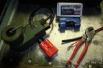
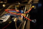
Below you can see the old and new wires, the tools I used to cut the heavy cable and crimp on connectors. You can also see the connector I made that allows the Ready Welder to plug directly into the slave port. The writing on the red connector says "+/- reversed, use only for flux core wire". The crimper works with 2 3/8" socket wrenches, and crimps up to 4/0 lugs. The wire cutters are basic economy model. I use them about once a decade, so I use a wire tie to keep them closed and sharp.

DSCF2815.jpgDSCF2813.jpg
 
Last edited:

Another Ahab

Well-known member
18,007
4,579
113
Location
Alexandria, VA
I contacted Leese Neville to ask about the Plan B Mod, in light of earlier posts in this thread suggesting it might cause problems. We're still talking, but after several e-mails and phone calls, I have some useful information to report.

  • They have excellent customer support.
  • Their voltage regulators are not adjustable.
  • Measured at the alternator, the 12V should put out 14.2V +/- 0.1V. (Mine does, 14.15V.)
  • A 12V alternator requires much heavier wires than a 24V alternator.
I upgraded the wire from the 12V alternator from the original 10G to 2G. With a running engine, I now get 0 volts between the alternator + and the front battery +. I get 0.2V between the alternator - and the front battery -. So the positive wiring looks good, but the negative needs work. I'll tear that apart and clean/lube those connectors next.
So, you're right on the money already then, right/
 

jpg

Member
611
15
18
Location
Boston, MA
So, you're right on the money already then, right/
Yes, the 12V alternator voltage regulator is performing as designed. The rear battery is seeing half a volt more charge than the front, with the engine at idle.

I still need to measure the voltages at load, and the Leece Neville folks have yet to answer the question about the voltage regulators conflicting with each other, but this is progress.
 

tim292stro

Well-known member
2,118
41
48
Location
S.F. Bay Area/California
I contacted Leese Neville to ask about the Plan B Mod, in light of earlier posts in this thread suggesting it might cause problems. We're still talking, but after several e-mails and phone calls, I have some useful information to report.
...

  • A 12V alternator requires much heavier wires than a 24V alternator...
Remember that when sizing your negative wire, you need to account for the loads and sources that pass through it (refer back to the loop drawings above). It'll need to support the proposed 24V alt AND the proposed 12V alt. (much thicker than either positive wire).

It is interesting to see how tight their regulation voltage is, it's half what I expected from them. Ont thing I was going to suggested is putting a current clamp meter on each positive alternator feed to find out what is doing the most work in your system.
 

Another Ahab

Well-known member
18,007
4,579
113
Location
Alexandria, VA
Remember that when sizing your negative wire, you need to account for the loads and sources that pass through it (refer back to the loop drawings above). It'll need to support the proposed 24V alt AND the proposed 12V alt. (much thicker than either positive wire).
Does this apply to Alternators only:

- or is it also recommended that battery leads have different sizes based on added extra loads (beyond OEM standard, like a crane, etc)?
 

tim292stro

Well-known member
2,118
41
48
Location
S.F. Bay Area/California
Batteries more specifically, or in the CUCV original wiring, the lower 12V battery & alternator...

For a series string you are current limited by the lowest capacity device in the string, but when you tap a battery in the string, you are drawing what the series string is supplying, plus whatever the tap is pulling (the lower battery would probably be the current limiting device with a 12V tap, so it and its cables work harder than the other battery). For a nested alternator setup, the negative to the lower battery has to pass the charge current demand for both series string batteries, but the lower 12V alternator is going to try and charge the lower battery too.

Jpg, you may find that if you size the negative cable properly that you can get away with the nested alternators, but your 160Amp 12V alternator will only run 12V loads once the lower battery is at equal charge to the upper battery (at which point the 24V alternator will take the rest of the load...). I'm interested to hear how LN handles the field current when the voltage is out of its control range (+/-0.1v). Always nice to find someone inside who will spill their technical data publically.

Here is an article from a guy at STMicroElectronics on how to build a modern alternator regulator. It's interesting and might provide more insight than my babbling :beer:

What I'm forecasting is that you will hear from the LN tech rep, is that the risk of the 12V alternator's lowest start-up field current may make it hard for even the 12V alternator to stay in regulation, and this pulsing of >14.4V will trick the 24V alternator into the load dump range of its regulation range, and the fight will ensue. I would be genuinely surprised to have you come back with advice from LN that the nested setup is okay - if so, I'll eat an extra taco (because let's be honest hats aren't that tasty... [thumbzup])
 
Last edited:

Csm Davis

Well-known member
4,166
393
83
Location
Hattiesburg, Mississippi
Might I add a little bit to this discussion about battery cable size, bigger is almost always better I am putting battery cables from 5 tons in my 1010 and have used bigger cables on most every automobile I have had for the last 20 years. For 12v to do the same work as 24v you need twice the amps which will require twice as big a wire gage for 12v as 24v
 

jpg

Member
611
15
18
Location
Boston, MA
Jett from Leece Neville called again. The guys who designed these voltage regulators had a discussion about our Plan B Mod. They never intended the alternators to be configured this way, and they never tested them in this configuration. Based on the voltages I measured, especially after upgrading to a heavier cable from the 12V positive, they say the Plan B Mod should cause no problems. We have their blessing.

As to sizing cable runs, Jett suggested measuring the voltage drop from the beginning to the end of the run. Half a volt loss is typical in automotive battery & charging cable runs. He pointed out that the important measurement is to measure voltage drop under heavy load. He suggested putting a load tester in place of the alternator, setting it to the alternator's max output, and measuring voltage loss then. He said Harbor Freight has a decent load tester for about $50. He also called it a "carbon pile".

I'll be working over my cables, upgrading where it seems like it will help, cleaning and lubing as I go.
 

tim292stro

Well-known member
2,118
41
48
Location
S.F. Bay Area/California
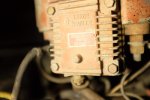
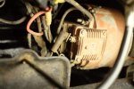
From that picture, the positive is at the top of the picture exiting the left side of the image, the ground is the fat cable at the bottom of the picture exiting to the right of the image (I may have + - reversed) - the little wire coming out from the case of the alternator going to the regulator is probably the field wire.
 
Top
AdBlock Detected

We get it, advertisements are annoying!

Sure, ad-blocking software does a great job at blocking ads, but it also blocks useful features of our website like our supporting vendors. Their ads help keep Steel Soldiers going. Please consider disabling your ad blockers for the site. Thanks!

I've Disabled AdBlock
No Thanks