• Steel Soldiers now has a few new forums, read more about it at: New Munitions Forums!

  • Microsoft MSN, Live, Hotmail, Outlook email users may not be receiving emails. We are working to resolve this issue. Please add support@steelsoldiers.com to your trusted contacts.

MEP-004A, No output

peapvp

Well-known member
Steel Soldiers Supporter
1,113
1,229
113
Location
Basehor, KS
Kris,

the Ohm reading with 2.1 Ohm is typical for the 15Kw and 30Kw units. The manual recommends disassembly of G1 in case of heavy dirt accumulation and final ultra sonic cleaning of all parts including the housing with coils. This is per Depot Level Maintenance - not field level maintenance.

The low internal resistance of the static exciter is usually to low for the commercial after market exciters. A Customer of mine in Texas usually has the static exciter rewound with smaller gauge wire which has then 25 Ohm resistance to work with the aftermarket units. He just did a 30Kw for a new Fire Station near Houston.

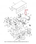
The VR Board is the circuit board on the sub-assembly - it is the board which is mounted horizontally.
 

peapvp

Well-known member
Steel Soldiers Supporter
1,113
1,229
113
Location
Basehor, KS
Kris,

I guess you meant by exciter the sub-assembly. The entire sub-assembly is actually the Voltage regulator which connects to the static exciter in G1. The static exciter in G1 is a stand alone part which can be easily removed when G1 has been removed from the Genset and the back cover has been removed.
 

Guyfang

Moderator
Staff member
Moderator
16,766
24,076
113
Location
Burgkunstadt, Germany

Guyfang

Moderator
Staff member
Moderator
16,766
24,076
113
Location
Burgkunstadt, Germany
Kris,

J16 is the large female amphenol connector which plugs into your vr unit it self - TB16 is according to the manual located in close proximity of where the entire VR Unit is mounted to the Genset Chasis and G1 itself as those two wire F1 and F2 come out of G1 and terminate on TB16. The manual does not show an exact location.

J16 Pinout from Front

View attachment 773599

"There is a principle which is a bar against all information, which is proof against all arguments, and which cannot fail to keep a man in everlasting ignorance—that principle is contempt prior to investigation."
Guys,

this is J13, not J16. Peter, are you using 007 Schmatices? The two wires in red, go to TB1. TB1 is the voltage change over board. That is mounted in the left rear door. Has a plastic cover on it to keep you from cooking yourself when you foolishly place your hand on it. Has a large amount of bolts and nut in it.
 

Guyfang

Moderator
Staff member
Moderator
16,766
24,076
113
Location
Burgkunstadt, Germany
Boy I'm relieved.
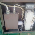
Peter the exciter seems to me being a swap to me. The inside of it is very dirty plus a orange round sticker on the outside. Not like the other boxes that are very clean.
It could have been swapped after the gen quit running correctly. Don't know for sure but highly suspect.
Next I will try to find the VR Board.
Kris
See post# 106.
 

peapvp

Well-known member
Steel Soldiers Supporter
1,113
1,229
113
Location
Basehor, KS
That was a typo with J16, J13 is correct and TB1 should be TB16 in the manual TM 9-6115-464-34.pdf Page 337 or 3-283
One of the many misprints in TM's.....

Guys,

this is J13, not J16. Peter, are you using 007 Schmatices? The two wires in red, go to TB1. TB1 is the voltage change over board. That is mounted in the left rear door. Has a plastic cover on it to keep you from cooking yourself when you foolishly place your hand on it. Has a large amount of bolts and nut in it.
 

peapvp

Well-known member
Steel Soldiers Supporter
1,113
1,229
113
Location
Basehor, KS
That was a typo with J16, J13 is correct and TB1 should be TB16 in the manual TM 9-6115-464-34.pdf Page 337 or 3-283
One of the many misprints in TM's.....
Actually it goes to TB1 on the sub-assembly and from there to all the other connecting points from the receptacle J13
Connector J13 R/S goes to TB 16 1+2
 

peapvp

Well-known member
Steel Soldiers Supporter
1,113
1,229
113
Location
Basehor, KS
Kris,

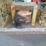
Yes, if there is no obvious damage to the VR Board or any other component on the sub-assembly. You cant test the function of the VR Board only after the transformer has been fixed
 

Guyfang

Moderator
Staff member
Moderator
16,766
24,076
113
Location
Burgkunstadt, Germany
Kris,

this is is what Peter is showing you. The picture on the left is the so called Excitor Assembly. Inside it, it broken down into two sub assembly's. The printed card is the VR. The rest of it is the Excitor. The Excitor in the G1, ( main generator) is a big coil, or coils. They are mounted on the end cover of the main gen. Easy to replace. They get voltage in the beginning, from S2. 24 VDC. When you let go S2, the VR is supposed to take over this funtion. The VR applies VDC to the Excitor coil, and through induction causes the windings in the main gen to produce power. Raising and lowering the VDC applied to the Excitor coil raise and lowers the output voltage. If I have missed something here Peter, chime in. I haven't even thought about this theory jazz for 30 years.
 

Guyfang

Moderator
Staff member
Moderator
16,766
24,076
113
Location
Burgkunstadt, Germany
Actually it goes to TB1 on the sub-assembly and from there to all the other connecting points from the receptacle J13
Connector J13 R/S goes to TB 16 1+2
ok. Will try and look up tb16. I THINK, it's mounted next to TB1. Just a short little terminal board with about 4 (?) wires on it.

Kris, the TB numbers should be right next to the TB's, on the relay table. The relay table is the flat surface all thes boxes are mounted to.
 

KLChurch

New member
475
2
0
Location
Montgomery/TX
Like I say I'm a mechanical Engineer, but when I went to college I wanted to be an electrical engineer and did not pursue it.
Mechanical was more natural for me.
Kris
 

peapvp

Well-known member
Steel Soldiers Supporter
1,113
1,229
113
Location
Basehor, KS
Guy, from what I gathered this is a Barrier Terminal Strip with two terminals only and is mounted between the Sub-assembly A11 and G1 the two static exciter wires F1 and F2 from G1 terminate on TB16 and are routed from there to the connector of J13 R/S
 

peapvp

Well-known member
Steel Soldiers Supporter
1,113
1,229
113
Location
Basehor, KS
Btw. thank you Kris and Guy - I finally got promoted to Sargent Major!

I am personally terrible at typing, I usually do this over the phone. The entire 100+ posts would have taken less then 10 minutes to check the exciter coil resistance this way. But anyway, thank you!
 
Top
AdBlock Detected

We get it, advertisements are annoying!

Sure, ad-blocking software does a great job at blocking ads, but it also blocks useful features of our website like our supporting vendors. Their ads help keep Steel Soldiers going. Please consider disabling your ad blockers for the site. Thanks!

I've Disabled AdBlock
No Thanks