• Steel Soldiers now has a few new forums, read more about it at: New Munitions Forums!

  • Microsoft MSN, Live, Hotmail, Outlook email users may not be receiving emails. We are working to resolve this issue. Please add support@steelsoldiers.com to your trusted contacts.

MEP-004A, No output

KLChurch

New member
475
2
0
Location
Montgomery/TX
Compared both boards in the exciter and the new one. Same numbers 30554-72-2616.
The new one has been tested and came with a strip chart reading.new exciter board.jpg
 

Guyfang

Moderator
Staff member
Moderator
16,766
24,072
113
Location
Burgkunstadt, Germany
Kris, This is also an option. Someone in the forum sent this to me. I didn't post his name, as he might not want that. But if it sound interesting, I can ask him if he would talk with you.


Guy,

I actually had the large transformer fail inside the static excitor and never found a replacement. So I upgraded to a newer style vr/excitor board. It takes out the entire excitor box. It worked. Part is ADVR-54 self excited automatic vr.
Hope this helps
 

peapvp

Well-known member
Steel Soldiers Supporter
1,113
1,229
113
Location
Basehor, KS
Our experience with any of the 00x Voltage Regulator Boards / System is as follows:

1. The first indication of a failing Voltage Regulator is that the Voltage can not be regulated/ selected over the original range.

The most common failure source (95%) at this stage is a broken lead on one off the axial mounted capacitors/resistors which are either epoxied or hot melt glued to the PCB.

After years of operation and storage, the component leads start to corrode and become fragile. The larger parts are more effected by this then the smaller axial resistors.

The lead usually breaks between the component and the solder connection, quite often on the bend.

The Voltage regulator usually keeps operating at this point with the effect that the voltage cannot be fully regulated or becomes to low, usually around 150VAC to 195VAC when Genset is set to 208/230 Three Phase or 240/120 Single Phase or idles over a +/- 20 V range.

As a result of prolonged operation, other parts get overloaded and then finally fail.

The second less common failure is a Semi Conductor Failure, which usually happens as the result of the above issue, but rarely (5%) by itself.

The best thing is to check all components for secure lead connections on the PCB and that the axial parts on the board are fixated so they cannot move by themselves, on a regular basis

We have also gotten 005/006/007 Voltage Regulators to be rebuilt from US coastal areas on which the Airframe Typ 2 Wire Harness had completely corroded and rotted away from prolonged exposure to salt in the air over a period of decades.

So did the iron core in the transformers.

I have to dig one out from an 006 which was beyond repair and post the pictures here

The VR is the most overlooked and unchecked item on those Genset because of its cover/enclosure and the mounting location which requires removal for inspection

An Hour spent removing, checking / cleaning / maintaining and re installing your VR can save you a lot of grieve.....


PS. A can of high grade contact lubricator for the amphenol connectors will make for a happy and piece full Genset Ownership experience
 

KLChurch

New member
475
2
0
Location
Montgomery/TX
Peavpv,
Thanks for the info. It is very telling. Hope someone will benefit from your post.
I wish I could understand it. Not saying you are not understandable. My fault. I am a mechanical engineer and a neophyte in this area problem solving.
Again thanks for the info.
Kris
 

KLChurch

New member
475
2
0
Location
Montgomery/TX
After re reading Peavpv write up should we be worried about that what I think is that great big capacitor? It is next to the fried transformer.

Kris
 

Guyfang

Moderator
Staff member
Moderator
16,766
24,072
113
Location
Burgkunstadt, Germany
After re reading Peavpv write up should we be worried about that what I think is that great big capacitor? It is next to the fried transformer.

Kris
In my experience, the Big Cap is very tough. Doesn't mean it can fail, but I have only replaced one, and it popped because it was in the way when I dropped an un isolated screwdriver into the exciter while testing in under load. My bad.
 

Guyfang

Moderator
Staff member
Moderator
16,766
24,072
113
Location
Burgkunstadt, Germany
Detail pictures of the pcb so we can zoom in on the parts....
Peter,

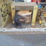
T2 in the exciter burned up. I think its T2 anyway. The big honking transformer. Kris's big problem is finding a replacement. Can you give us and sort of help there? Kris has a few pictures a ways back in another thread, maybe he can put them in here. Heck, I can also. exciter6.jpg

Nothing else SEEMS to be damaged. But you can not start to fix it without the Transformer.
 

peapvp

Well-known member
Steel Soldiers Supporter
1,113
1,229
113
Location
Basehor, KS
One thing to remember:

The MEP 00x Series came into service in the 1960's
In our instance, those voltage regulators we have been asked to rebuilt / trouble shoot were indeed 40+ years old and were in service in Vietnam
I am sure Guy can tell us exactly of what year they came into service.
 

Guyfang

Moderator
Staff member
Moderator
16,766
24,072
113
Location
Burgkunstadt, Germany
View attachment 773437View attachment 773438
JUst discovered this The part number on the cover, in the left picture is right. Its for the cover itself. Just looked it up.
One number on the cover and another on the side of the exciter..
Should they both be the same number?
Just maybe a clue that the unit was a swap before or after the gen not running on the gen side.
Kris
.
 

Guyfang

Moderator
Staff member
Moderator
16,766
24,072
113
Location
Burgkunstadt, Germany
One thing to remember:

The MEP 00x Series came into service in the 1960's
In our instance, those voltage regulators we have been asked to rebuilt / trouble shoot were indeed 40+ years old and were in service in Vietnam
I am sure Guy can tell us exactly of what year they came into service.
The NSN was issued in 1968. We started to recive them here in Germany in 1974. Or that's when I saw them for the first time. The first issues went to State side units. We got our 60 KW's in 74 in any case.
 

peapvp

Well-known member
Steel Soldiers Supporter
1,113
1,229
113
Location
Basehor, KS
Ok,
This NSN 5950-00-600-0840
Primary: 208VAC
Secondary: 124VAC Split Core
Frequency: 50Hz/60Hz

have to check the VA Rating (guess 50VA to 100VA). Any Step Down Single Phase Transformer with a split secondary and same VA / Frequency rating will work here

However, for a transformer in this size (VA) to fail like this here points to a severe short on the secondary side
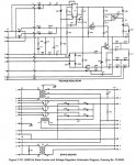
I am looking at the schematic and this points to Q4 and a few other semi conductors.

The TAP X2 on the Transformers secondary directly connects to your exciter coil via J13/R...
J13/S is the common

Have you checked the DC Resistance of your exciter Coil? Not sure what this should be, but more then a few Ohms

And, ALL Electrolytic Caps Dry Out over time, meaning their Capacitance / ESR changes as the Electrolyte dries out

A large size capacitor has to be reformed if the system has not been powered up in a period of 2+ years or if the Capacitor has passed his shelf live, which is usually at a minimum of 2000 hours at 80 Degree C - time increases with lower storage temperature - not a linear function - this is described in the capacitor manufacturers data sheet for that particular Capacitor Family

A Capacitor is reformed by applying the rated DC Voltage and limiting the current to 1 miliAmpere for anywhere between 96 Hours to 400 Hours depending upon Capacitance.


004a vr repair.png004A VR.jpg004A xc.jpg
 

KLChurch

New member
475
2
0
Location
Montgomery/TX
Im pretty sure the gen was not started up for over two years before I got it. It had department of New York City written on the side of it when I got it. It was sitting in Columbus Ohio for years without use. That's why maybe it only showed 300 hours.
No real history on the gen.
Kris
 
Top