• Steel Soldiers now has a few new forums, read more about it at: New Munitions Forums!

  • Microsoft MSN, Live, Hotmail, Outlook email users may not be receiving emails. We are working to resolve this issue. Please add support@steelsoldiers.com to your trusted contacts.

MEP-004A, No output

KLChurch

New member
475
2
0
Location
Montgomery/TX
Don't know what an exciter coil is. You mean what I have been calling a transformer that it toast? Still trying to figure out what to do about it. Cant find a replacement that I can afford.
Kris
 

peapvp

Well-known member
Steel Soldiers Supporter
1,105
1,216
113
Location
Basehor, KS
No, the coil inside your generator itself. It has two wires coming out on the left of G1 - see diagram below - if this internal coil is burnt out / shortened then you have to disassemble your generator and have it rewound or get a new generator

The transformer is just the visible casualty in a much larger problem you got

This transformer here would work as replacement:

https://www.automationdirect.com/ad...sformers/240x480_vac_to_120x240_vac/sp100mqmj

But again, just replacing the transformer is not going to fix your problem....

>>>>>>>>>>>>>>>>>>>>>>>


Moderator's note: Above link has been determined to be the wrong transformer to buy.
Please refer to Post #271 (of this same thread), which has the correct info.
 
Last edited by a moderator:

KLChurch

New member
475
2
0
Location
Montgomery/TX
Now Im getting scared. In research my mentor always said don't go forward until you figure out the real problem.
So how do we check the coil inside the gen?
Kris
 

peapvp

Well-known member
Steel Soldiers Supporter
1,105
1,216
113
Location
Basehor, KS
So how do you check it? Burn marks, Muti meter, or what. Also where is it at?
Kris
Kris,
here it goes:

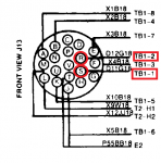
1. On J13 locate the two pins R and S ( That's the connector, not the receptacle on the voltage regulator assembly)

2. Set your multi meter to Ohm

3. Measure Resistance between R and S
If meter indicates infinite resistance then locate TB-16 Terminal 1 and 2 - I am not exactly sure where Tb 16 is located but it is either closer to Generator G1 or the VR Unit

repeat Ohm measurement between TB16-1 and TB16-2 - TB 16 has only two terminals and is a Barrier Type Terminal
check also that two wires F1-16 and F2-16 acre connected to TB16-1 (F1-16) and TB16-2(F2-16)
these two wires F1-16 and F2-16 are the wires from your exciter coil.
If the Ohm reading on these two is:

Infinite Ohm: Exciter Coil Burnt out and Open - replace or have G1 rewound

less then 1 Ohm: Exciter Coil Shorted - replace or have G1 rewound

if above 1 Ohm but less then 4 Ohm: Exciter Coil OK - Your Voltage Regulator PC Board and or other parts in the VR Assembly need to be replaced / overhauled


above 4 Ohm: Exciter Coil is going to fail - have an expert check G1 for further assessment and possible repair

004A xc detail.jpgexciter resistance.jpg

Peter
 
Last edited:

Guyfang

Moderator
Staff member
Moderator
16,696
23,904
113
Location
Burgkunstadt, Germany
Btw. how is your exciter coil doing?
Peter, Kriss,

I think the Excitor coil should be good. Dosnt mean it should not be tested, but when Kris holds the S2 up in the start position, and S9-1 contacts reverse, there is voltage on the meter as long as he holds up the S2. That's the 24 volts directly from S2, to the S9-C pin in S9. When you let go S2, normally the volt reg is supposed to take over the excitation process. That's not happening.
 

KLChurch

New member
475
2
0
Location
Montgomery/TX
Guyfang, Peter
I was tossing and turning thinking about the same thing. Why was I getting 100 volts and was able to increase to 105.
But I like to turn over all the rocks.
Can you tell me where J16 is at? And TB16.
Kris
 
Last edited:

KLChurch

New member
475
2
0
Location
Montgomery/TX
I found 2 red lettering wires coming out of the exciter box. D11G16 and D12G16 not P11G16 and P12G16
All the other wires have black lettering.
Could the schematic be wrong?
So Im assuming J16 connects to J13.
Kris
 

peapvp

Well-known member
Steel Soldiers Supporter
1,105
1,216
113
Location
Basehor, KS
Kris,

J16 is the large female amphenol connector which plugs into your vr unit it self - TB16 is according to the manual located in close proximity of where the entire VR Unit is mounted to the Genset Chasis and G1 itself as those two wire F1 and F2 come out of G1 and terminate on TB16. The manual does not show an exact location.

J16 Pinout from Front

J13.png

"There is a principle which is a bar against all information, which is proof against all arguments, and which cannot fail to keep a man in everlasting ignorance—that principle is contempt prior to investigation."
 

peapvp

Well-known member
Steel Soldiers Supporter
1,105
1,216
113
Location
Basehor, KS
Checked R and S with a digital ohm meter.
I got 2.1 ohms.
Kris
That's good news! Ok, now you need a new transformer.

Then the next test would be actually to test the VR Board and that requires locating TB16 and disconnecting the two wires F1 and F2 - the Voltage on TB16-1 and TB16-2 should be 30 VDC during start

A Transformer usually doesn't blow like this, not even a Chinese made one, unless there is something else wrong....

Saying, there is an underlying cause to this
 

KLChurch

New member
475
2
0
Location
Montgomery/TX
Boy I'm relieved.
Peter the exciter seems to me being a swap to me. The inside of it is very dirty plus a orange round sticker on the outside. Not like the other boxes that are very clean.
It could have been swapped after the gen quit running correctly. Don't know for sure but highly suspect.
Next I will try to find the VR Board.
Kris
 
Top
AdBlock Detected

We get it, advertisements are annoying!

Sure, ad-blocking software does a great job at blocking ads, but it also blocks useful features of our website like our supporting vendors. Their ads help keep Steel Soldiers going. Please consider disabling your ad blockers for the site. Thanks!

I've Disabled AdBlock
No Thanks