• Steel Soldiers now has a few new forums, read more about it at: New Munitions Forums!

  • Microsoft MSN, Live, Hotmail, Outlook email users may not be receiving emails. We are working to resolve this issue. Please add support@steelsoldiers.com to your trusted contacts.

MEP-004A, No output

KLChurch

New member
475
2
0
Location
Montgomery/TX
Guyfang,
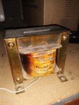
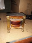
Maybe I'm jumping the gun but I bought a 3 phase to single phase transformer. It will be delivered today.
One heavy sucker. Got it used from ebay. This will be installed in a room outside the house that will be close to the main breaker box (within 5 feet). The room is fully enclosed, lockable and fire proof.
I will have to buy another breaker box to segregate the breakers I want to use during a blackout because 20k may not be enough power.
Kris
 

Guyfang

Moderator
Staff member
Moderator
16,765
24,069
113
Location
Burgkunstadt, Germany
OH ye of little faith!

Nothing wrong with planning ahead. When Peter is done with you, I am going to give you some small tasks to make sure we have a A1 gen set. Then you are going to be golden!

Got to BELIEVE, brother! Got to Believe!
 

peapvp

Well-known member
Steel Soldiers Supporter
1,113
1,229
113
Location
Basehor, KS
Test 3 - Repair and Test of an A11 Static Exciter Unit for MEP004A/005A

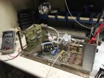
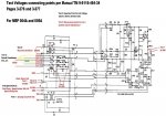
Today I was finally able to do the Boost Test as per Manual TM 9-6115-464-34 Pages 3-276 and 3-277

and Thank You Brian for fixing Q4 in the schematic. I found this schematic in the -34 Manual from the 005A (30KW) and got so excited that this drawing actually had the Filter Unit E2 ( C3, C4, C5, C6) 0.01uF 600VAC included. However, when you look at the A11 Base you can see only a label E2 on the Capacitor Assembly but no labels for the 4 Cx's...
I saw the issue with Q4 and thought I am going to fix this last but then forgot it until you reposted the schematic because I got preoccupied with all the test things I added.....

Now we got a complete and verified schematic of A11 - Thanks again Brian

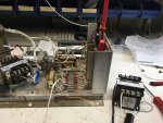
Back to the Boost test, Setup and testing as follows:

Test 3.jpgTest 3a.jpg

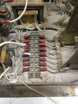
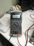
So, I tested CT4 first going through my 1K 10W 10 Turn Potentiometer. I applied 11.93 VAC via the Terminal Board which again was easier then going through J13

70148318_481229942432541_5367103390641815552_n.jpg70626923_636042823551180_2163580369381621760_n.jpg69837251_489606508284141_7330215581662052352_n.jpg

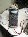
And we measured across the the heatsinks:

70025747_666112733909025_370315606429270016_n.jpg70170675_385763032320478_7331954579560464384_n.jpg

We measured 9.22 VDC - Test GOOD


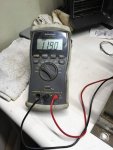
Next was CT5, we applied 11.90 VAC

69826480_2414375872170535_3813321868060917760_n.jpg

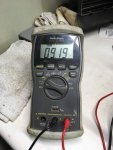
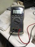
and we measured: 9.19 VDC Test OK

69824363_3153768051306505_5891087996299509760_n.jpg

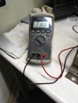
Last was CT6 and we applied 11.88 VAC

70501997_494054288095027_8916980524635914240_n.jpg

and we measured 9.19 VDC Test OK

70167506_375248983377179_2835897958438797312_n.jpg


The transformer T1 has a very low DC Resistance across its Primary winding's ( 1 to 2 Ohm ) which started to heat up my 10W Potentiometer and caused the AC Voltage applied to drop from 11.93 VAC to 11.88 VAC

This drop is so small that it can be ignored

The worst deviation is from the required 9.3 VDC to 9.19 VDC which is -1.07%
which is virtually irrelevant as we were at 11.88 VAC input Voltage instead of 12 VAC which is -1.01%

so, we are dealing with a 0.07% deviation

It couldn't be any better

So, Kris's A11 is all tested and good now

Last thing on the List is modifying T2 and then repeating Test 2 to verify the correct operation of the Power Test with the modified T2
 
Last edited:

flydude92

Member
117
9
18
Location
Waterville, Ohio
Now we got a complete and verified schematic of A11
Well, almost.

I'm planning on using the schematic to repair a couple regulator
cards so I was looking it over again and noticed a few more omissions.

There is no connection between Q5 and C10.
Although VR1 and VR3 are listed on the schematic the components are not, so I added them.

Hopefully that's everything.
Brian
 

Attachments

peapvp

Well-known member
Steel Soldiers Supporter
1,113
1,229
113
Location
Basehor, KS
Great! I saw only Q5. I don't think the 004A schematic got those errors here but I would have to look. I was primarily concerned with the testing aspect of the entire A11 as we had anticipated that Kris's VR Board was still OK but needed to find the cause of T2 overheating, which was C2.

Thanks Brian! Good work!

Well, almost.

I'm planning on using the schematic to repair a couple regulator
cards so I was looking it over again and noticed a few more omissions.

There is no connection between Q5 and C10.
Although VR1 and VR3 are listed on the schematic the components are not, so I added them.

Hopefully that's everything.
Brian
 

Guyfang

Moderator
Staff member
Moderator
16,765
24,069
113
Location
Burgkunstadt, Germany
The TM's for the 004A and 005A gen sets suck. When ever you find something wrong or missing with a schematic, for instance on a 004A, go to the 005A schematic. Its almost always right on the other schematic. And vice versa. Same thing with the -24P's. Kris and I found at least two mistakes on the 004A schematics.

The 006A book was worse, and there was no place to go to check it, other then asking a CECOM rep. The -12 TM had 18 changes. Some of course were due to upgrades, and additions. But had you ever updated a basic -12 from no changes to the last change, and I have, reading the inserted pages was eye opening. So it never hurts to open up the other TM when working on a 004A or 005A.
 

Guyfang

Moderator
Staff member
Moderator
16,765
24,069
113
Location
Burgkunstadt, Germany
Well, almost.

I'm planning on using the schematic to repair a couple regulator
cards so I was looking it over again and noticed a few more omissions.

There is no connection between Q5 and C10.
Although VR1 and VR3 are listed on the schematic the components are not, so I added them.

Hopefully that's everything.
Brian

Brian,

Great job! If you have the capability, could you add a Pointy Finger to let people know whats been added or changed? Its what gets done when CECOM makes a change. Its a good idea, as then someone KNOWS what got changed, instead of just knowing SOMETHING got changed. If you don't know what I mean, I will find an example when I get to my computer. Tablets suck for that kind of thing.
 

peapvp

Well-known member
Steel Soldiers Supporter
1,113
1,229
113
Location
Basehor, KS
Guy,

There is also an error in DC Schematic for all three Versions, the 004A. 005A and 006A

It is the momentary Toggle Switch S3 which has two pins swapped - We found this out when we developed the Auto / Remote Start Kit for those Genset's a few years ago:


FO6.jpg


The TM's for the 004A and 005A gen sets suck. When ever you find something wrong or missing with a schematic, for instance on a 004A, go to the 005A schematic. Its almost always right on the other schematic. And vice versa. Same thing with the -24P's. Kris and I found at least two mistakes on the 004A schematics.

The 006A book was worse, and there was no place to go to check it, other then asking a CECOM rep. The -12 TM had 18 changes. Some of course were due to upgrades, and additions. But had you ever updated a basic -12 from no changes to the last change, and I have, reading the inserted pages was eye opening. So it never hurts to open up the other TM when working on a 004A or 005A.
 

Guyfang

Moderator
Staff member
Moderator
16,765
24,069
113
Location
Burgkunstadt, Germany
View attachment 15 30KW MilStd DC.pdf

What we really need to do is combine everyone's corrections into this little helpful item. The troubleshooting of the 004-006 would be much simplified if the terminal numbers were included. The color coded schematics like this one are very helpful. Or at least for me. I just do not have the knowledge or the program to do so.
 

peapvp

Well-known member
Steel Soldiers Supporter
1,113
1,229
113
Location
Basehor, KS
Details of NOS Voltage Regulator Board

This should be of interesst to Brian to assist with the repair of the two VR Boards he got:

Kris had bought already a replacement Voltage Regulator Board on eBay prior to me getting involved in this thread here and had shipped it up here with his A11 Unit in the case that the original VR Board was bad and needed to be replaced.

However, I did the Capacitor tests first as a preliminary test which confirmed that C2 had dried out. So, we proceeded to do all other test's with the original VR Board currently installed and that checked out OK (See all tests 1 to 3 in this thread)

Now, the NOS from eBay had a 3.5 foot long print out on millimeter paper which I didn't get to look at until today since it was still stapled to the ID Tag on the Board.

And then came the surprise when I looked at the date the print was created! What a coincidence!

70343184_727249767723981_1962366597582553088_n.jpg

Here is another detail
70445506_490046105109422_1395819351352803328_n.jpg

And then this! Already in 1991! Holly ****! This is the time this VR Board was assembled and no part has ever been replaced - still the original conformal coating! Unbelievable!


70588628_2445540808846719_973511726991409152_n.jpg


Brian, I will post more details later tonight. I have to take care of a few other things first and Guy, I can and I will when I find the time....
 

KLChurch

New member
475
2
0
Location
Montgomery/TX
So maybe it would be good to get some readings on it that is not normally done?
You can thank Wild Bill Clinton for giving away our trade secrets to our enemies.
Kris
 

peapvp

Well-known member
Steel Soldiers Supporter
1,113
1,229
113
Location
Basehor, KS
Details of NOS Voltage Regulator Board

Ok, so here is the recorder print out - the whole print is app 1066.8 millimeters / 5 = 213.36 seconds = 3 minutes 33.36 seconds

The entire test took app 3.5 Minutes

What I can tell you about this test:

1. This was a bench test, testing only the VR Board without A11 in a special test fixture

2. This is a classical QA Pass/Fail Test

3. Top Channel is recording a Clock / Square Wave Generator

4. Bottom Channel is a output trigger based on the above signal Generator which is dependent on input signals


What I don't know is, where the two test points are, which recorded the two channels
Neither can I tell you the actual Voltage Levels measured

My best guess for the test point for the top channel was/is most likely around Q3, C4, CR9, R8, R10, R14, C8, R15, C9, CR11, Q4 and R20

My best guess for the test point for bottom channel was/is where Q4, R20, R18 and R19 connect together - this is the signal to the gates of the two SCR's Q1 and Q2

Now Brian, it may be a good time to get the two channel scope out and find out where to apply 24 VDC to the board and see what you find!

Would be nice to see your results, findings and conclusions!

70964041_1155968918124885_8631586093914914816_n-horz.jpg
 

flydude92

Member
117
9
18
Location
Waterville, Ohio

Kris
I don’t mean to step on your thread but this relates to T2 and C2.

A few years ago I was working on my generator (an 005) fixing problems I had so I had the exciter/VR open
while I worked. I could see the T2 transformer was getting darker as the days went by. Due to age
I decided to replace all the capacitors in the VR including C2 not realizing the affect it had on T2.
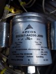
The date code on it was 7625.
I replaced it with # B32361-A4206-J080. (in case your interested Peter)
I replaced the T2 transformer with an NOS transformer I bought on EBay for $80. This setup has worked
fine for years although I did add the fuse Peter suggested recently.

I have a spare exciter/VR assembly although the VR didn’t work. I installed the fuse.
I replaced C2 with the expensive one you suggested and the old C2 didn’t have any info on it at all. I also have
two extra VR’s that need work. One of them I tested a couple days ago. I purchased it on EBay a few years ago
from someone that said it came out of a working generator. (it didn’t)

First I replaced all the capacitors. Then I ran test one and got 22V as expected. I ran test 2 but instead of
getting 48V I got 0. Turns out it blew the fuse. (thank you, thank you, thank you for the fuse suggestion Peter)

Both Q1 and Q2 (G1/G2 depending on which schematic you look at) were shorted between the
cathode and anode. I received the replacements from Mouser today and they fixed the problem. All test
voltages are good.

Installing the fuse is a must as far as I’m concerned.

Brian
 

Attachments

peapvp

Well-known member
Steel Soldiers Supporter
1,113
1,229
113
Location
Basehor, KS
Thank you Brian for the info!

Could you do me a favor and measure the DC Resistance on your T2 between H1 + H2, X1 + X3, X1 + X2 and X2 + X3 so I can add this info in the documents?

Also, what size (amperage) fuse are you using on your working system? My calculations yielded app. 750mA of power consumption on T2 H1 when at 208VAC

So, a 1 Amp Fuse should be fine - I just would like to double check this with your experience as I am not sure if there are any surge currents possible in this system ( I doubt it though)

Thanks Peter


Kris
I don’t mean to step on your thread but this relates to T2 and C2.

A few years ago I was working on my generator (an 005) fixing problems I had so I had the exciter/VR open
while I worked. I could see the T2 transformer was getting darker as the days went by. Due to age
I decided to replace all the capacitors in the VR including C2 not realizing the affect it had on T2.
The date code on it was 7625.
I replaced it with # B32361-A4206-J080. (in case your interested Peter)
I replaced the T2 transformer with an NOS transformer I bought on EBay for $80. This setup has worked
fine for years although I did add the fuse Peter suggested recently.

I have a spare exciter/VR assembly although the VR didn’t work. I installed the fuse.
I replaced C2 with the expensive one you suggested and the old C2 didn’t have any info on it at all. I also have
two extra VR’s that need work. One of them I tested a couple days ago. I purchased it on EBay a few years ago
from someone that said it came out of a working generator. (it didn’t)

First I replaced all the capacitors. Then I ran test one and got 22V as expected. I ran test 2 but instead of
getting 48V I got 0. Turns out it blew the fuse. (thank you, thank you, thank you for the fuse suggestion Peter)

Both Q1 and Q2 (G1/G2 depending on which schematic you look at) were shorted between the
cathode and anode. I received the replacements from Mouser today and they fixed the problem. All test
voltages are good.

Installing the fuse is a must as far as I’m concerned.

Brian
 

peapvp

Well-known member
Steel Soldiers Supporter
1,113
1,229
113
Location
Basehor, KS
and Brian one more question which would greatly enhance the testing. Could you please tell me of what the AC current is on H1 in Test 2 when you put a amp meter in series with the potentiometer and H1? This way we would have an additional reference value which could give clues to hidden issues even when we get 48Volts on R/S. Thank You!


Kris
I don’t mean to step on your thread but this relates to T2 and C2.

A few years ago I was working on my generator (an 005) fixing problems I had so I had the exciter/VR open
while I worked. I could see the T2 transformer was getting darker as the days went by. Due to age
I decided to replace all the capacitors in the VR including C2 not realizing the affect it had on T2.
The date code on it was 7625.
I replaced it with # B32361-A4206-J080. (in case your interested Peter)
I replaced the T2 transformer with an NOS transformer I bought on EBay for $80. This setup has worked
fine for years although I did add the fuse Peter suggested recently.

I have a spare exciter/VR assembly although the VR didn’t work. I installed the fuse.
I replaced C2 with the expensive one you suggested and the old C2 didn’t have any info on it at all. I also have
two extra VR’s that need work. One of them I tested a couple days ago. I purchased it on EBay a few years ago
from someone that said it came out of a working generator. (it didn’t)

First I replaced all the capacitors. Then I ran test one and got 22V as expected. I ran test 2 but instead of
getting 48V I got 0. Turns out it blew the fuse. (thank you, thank you, thank you for the fuse suggestion Peter)

Both Q1 and Q2 (G1/G2 depending on which schematic you look at) were shorted between the
cathode and anode. I received the replacements from Mouser today and they fixed the problem. All test
voltages are good.

Installing the fuse is a must as far as I’m concerned.

Brian
 

flydude92

Member
117
9
18
Location
Waterville, Ohio
Now Brian, it may be a good time to get the two channel scope out and find out where to apply 24 VDC to the board and see what you find!
Would be nice to see your results, findings and conclusions!
mmmmmmmmmmmmmmmm

A scope is on my wish list for Christmas. Not sure if you could wait that long. :shrugs:

Brian
 

flydude92

Member
117
9
18
Location
Waterville, Ohio
Peter,

I will get the information you need later this morning.

I put a 5 amp in my working system (I probably should lower that) and had a 3 amp fuse during test 2 when it failed.

Brian
 

flydude92

Member
117
9
18
Location
Waterville, Ohio
If you have the capability, could you add a Pointy Finger to let people know whats been added or changed?
If you don't know what I mean, I will find an example when I get to my computer.
I believe I know what you mean but when you have time send an example just in case.

Thanks,
Brian
 

KLChurch

New member
475
2
0
Location
Montgomery/TX
Brian,
You are not stepping on this thread. I believe yall are documenting very useful and important information.
Maybe even I may be able to understand it.
 

flydude92

Member
117
9
18
Location
Waterville, Ohio
Peter,

Here are the measurements you requested:

H1 / H2 1.8 ohm
X1 / X3 .7 ohm
X1 / X2 .4 ohm
X2 / X3 .4 ohm

I measured 588 mA at H1 (never fluctuated)

Let me know if you need anything else.

Brian
 
Top
AdBlock Detected

We get it, advertisements are annoying!

Sure, ad-blocking software does a great job at blocking ads, but it also blocks useful features of our website like our supporting vendors. Their ads help keep Steel Soldiers going. Please consider disabling your ad blockers for the site. Thanks!

I've Disabled AdBlock
No Thanks