• Steel Soldiers now has a few new forums, read more about it at: New Munitions Forums!

  • Microsoft MSN, Live, Hotmail, Outlook email users may not be receiving emails. We are working to resolve this issue. Please add support@steelsoldiers.com to your trusted contacts.

Picked up 6 MEP-802A gensets and will be documenting making them all runners here

pclausen

Well-known member
Steel Soldiers Supporter
452
281
63
Location
Afton, VA
I have been spraying the outside of S8 with this:
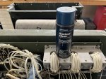
IMG_0604.JPG

And worked the switch probably over 100 times at this point, but still get those messed up readings.

I guess the cleaner is not getting into the switch itself and I need to take it apart to clean the contacts?

Is there a thread on here of someone taking one of these apart? Guy indicated it was doable, but challenging.
 

pclausen

Well-known member
Steel Soldiers Supporter
452
281
63
Location
Afton, VA
Thanks for those pics Kurt! I can see where I should concentrate my spraying of the contact cleaner. I'm going to keep at that for a bit longer before contemplating tearing one apart. That's a lot of parts per layer!
 

pclausen

Well-known member
Steel Soldiers Supporter
452
281
63
Location
Afton, VA
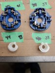
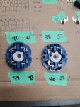
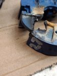
No luck spraying into the contact openings. So I opted to pull the switch. Here's one side:

IMG_0605.JPG

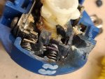
Other side:

IMG_0606.JPG

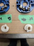
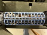
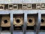
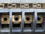
Close up of 8 in the "closed" position:

IMG_0609.JPG

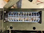
And open position:

IMG_0610.JPG

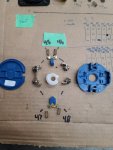
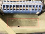
Check out the rust dust below where I had the switch when just doing a single position 3 to position 1 change:

IMG_0611.JPG

Pretty sure I'll need to take it apart to determine if it is salvageable or not.
 

kloppk

Well-known member
Steel Soldiers Supporter
2,145
3,526
113
Location
Pepperell, Massachusetts
Since you can see the contacts set the switch so 8 is "closed" and then look into cavity by 7 and see if it appears "closed".
If so I'd then check continuity from 7 to 8.
If no continuity, then I'd run a point file or something between the contacts and then recheck continuity.
 

Guyfang

Moderator
Staff member
Moderator
16,755
24,064
113
Location
Burgkunstadt, Germany
There is no way 3 switches can be bad. I have only seen maybe 3 bad switches in all the time I worked on this set. Dirty, funky, yes. All bad? No. So, that leaves only:
1. You not hitting the right places to measure ohms.
2. The S8 switch schedule is wrong.
3. Switch position is wrong when measuring.

But 3 switches bad, all in the same place at the same time? Stop it.
 

pclausen

Well-known member
Steel Soldiers Supporter
452
281
63
Location
Afton, VA
Filing all the contact points did the trick! At first it didn't, but after keeping at it for a good 30 seconds per contact set, I started showing continuity. So I did all 48 contact pairs (46 actually since 19/20 is blank). After doing them all, I tested for continuity in all settings, and everything looks good now.

Sprayed all contact with contact cleaner just for good measure.

Looks like I'll rinse and repeat for the set with low compression when I get that far.

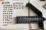
Now to put it all back together again.

IMG_0613.JPG

At least I didn't tear the entire switch apart!
 

robertsears1

Active member
255
119
43
Location
Near Apex/NC
I have taken apart 2 switches like that but they are only1/3 the length. Somehow I got one back together and the other still sits in a jar. That will be extremely difficult to reassemble!
 

pclausen

Well-known member
Steel Soldiers Supporter
452
281
63
Location
Afton, VA
Got the switch put back in and wired. I verified I had continuity where expected on TB3.

Fired it up, and what do you know, I'm finally making power! Measured 240V across L1 and L3 and 120V between those two and Neutral on the main output terminals.

IMG_0614.JPG

None of the gauges work, so that's next, but I'm very glad to finally be making power!
 

pclausen

Well-known member
Steel Soldiers Supporter
452
281
63
Location
Afton, VA
Turns out, except for the ammeter, all the gauges in my spare set are shot. And the ammeter shows that the alternator isn't charging the batteries while the set is running, so I'll be swapping that over from the spare set as well.

At least the Frequency Transducer is working as I'm seeing about 0.11 Ma when at 60 Hz and increasing to about twice that at 65 Hz. Also seeing 240 VAC across the terminals on the AC Volt Meter.

Don't know about the load meter yet, since I don't really want to put a load on this until I have the other gauges working, at least the engine ones.

Datcon Oil Pressure Gauge 24V 240-33.5 Ohms 0 - 80 PSI 52mm Black Bezel101574$33.36
Datcon Water Temperature Gauge 24V 100-280 degrees F Black Bezel101582$33.36
Datcon Fuel Gauge 24V 240-33.5 Ohms 52mm Black Bezel101584$33.36
Ideal Frequency Meter 36.1912NSN 6625-01-038-6869Unoptanium
Ideal Volt Meter 36.1884NSN 6625.01.038.6826Unoptanium

vehiclecontrols.com have a decent deal on the engine gauges, but those large indicators seem to be hard to source, at least I'm not having much luck.

I'll probably steal gauges from one of my working sets just to complete the load testing on this unit, to make sure I'm not in for additional surprises!
 

nextalcupfan

Well-known member
348
506
93
Location
NW Missouri
I found these on Mouser and they look like they would work, unfortunately they aren't stocked anymore so I'm not sure if you can still get them.

EDIT:
I just found out the frequency meter won't work with the stock wiring on a 80xx set.
I didn't know the stock gauge used a frequency determining transducer with the stock meter.
The meter I linked says 120v input which tells me its supposed to be hooked directly to 120V AC.
Now it really wouldn't be that hard to either extend the wiring from the transducer or find some other 120V AC source but I just thought I would mention it.
 
Last edited:

nextalcupfan

Well-known member
348
506
93
Location
NW Missouri
I've been thinking about this one myself.
Installing it where the Voltmeter goes should work without compromising the original panel info too much (I really don't want to give up the factory %rated current meter)

And this for replacing the Frequency Meter.

I checked the cutout dimensions and its basically a square of the hole already in the gauge panel.

They look kinda cheap but not too cheap if you catch my meaning.
You can get them with a green background that kinda matches the theme of the set too, which is nice.
 

pclausen

Well-known member
Steel Soldiers Supporter
452
281
63
Location
Afton, VA
Those are very cool looking digital gauges! Might consider those for my "keeper" 803 and 802 sets, depending on how many other failed gauges I have in the other sets I'm fixing up.
 
Top
AdBlock Detected

We get it, advertisements are annoying!

Sure, ad-blocking software does a great job at blocking ads, but it also blocks useful features of our website like our supporting vendors. Their ads help keep Steel Soldiers going. Please consider disabling your ad blockers for the site. Thanks!

I've Disabled AdBlock
No Thanks