• Steel Soldiers now has a few new forums, read more about it at: New Munitions Forums!

  • Microsoft MSN, Live, Hotmail, Outlook email users may not be receiving emails. We are working to resolve this issue. Please add support@steelsoldiers.com to your trusted contacts.

Picked up 6 MEP-802A gensets and will be documenting making them all runners here

pclausen

Well-known member
Steel Soldiers Supporter
452
281
63
Location
Afton, VA
Yikes, that does NOT look good.

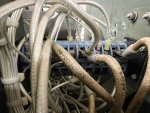
I started looking at S6 and the first wire I looked at was 171A. It was wired to terminal 32, which also had a black jumper wire going to terminal 30:

IMG_0568.JPG

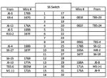
Looking at the wiring diagram, I see the following:

S6 wiring.jpg

So as I check each wire, it's ok to find a jumper wire going from an unlabeled terminal in the chart above, to the one that shows the actual wire #?

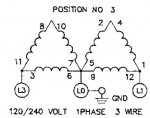
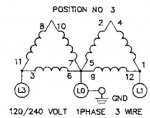
Should I perhaps try disconnecting the 12 leads from the stator and connect them like this:

1phase3wire.jpg

So see if a) the set no longer bogs down, and b) see if I get the expected voltages?
 

DieselAddict

Well-known member
Steel Soldiers Supporter
2,530
2,055
113
Location
Efland, NC
If you disconnect everything I'd test all the windings. Make sure they meet spec on resistance and aren't shorted together. From there you can choose whether to go back with the reconnect switch or make the voltage config permanent.
 

pclausen

Well-known member
Steel Soldiers Supporter
452
281
63
Location
Afton, VA
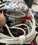
I looked at S8 and one thought I had was that perhaps that switch has an issue. After all, this particular unit had no top panel and had been sitting outside, which is why all the fasteners are rusted. It doesn't look that bad from the outside:

IMG_0564.JPG

The switch does turn between the 3 positions, but it does take some effort. Quite a bit more than my other units.

But yeah, I'll test the ohms between the winding first to make there that's not the root cause. If the issue is there, then there is no point checking the stuff downstream from it. Looks like I should expect to see between 0.37 and 0.50 Ohms between each wire pair.
 

DieselAddict

Well-known member
Steel Soldiers Supporter
2,530
2,055
113
Location
Efland, NC
One other thing to check is where the wires go down to the generator head. I’ve had a couple of units showing chafing against sharp edges.
 

pclausen

Well-known member
Steel Soldiers Supporter
452
281
63
Location
Afton, VA
Thanks guys. I have no chafing of the 12 wires. They are routed through 2 loops with rubber linings and not touching the metal at all.

I pulled all 12 leads from the main stator and measured the following resistances:

T1-T40.4 Ohm
T2-T50.4 Ohm
T3-T60.5 Ohm
T7-T100.5 Ohm
T8-T110.4 Ohm
T9-T120.3 Ohm

That last one bounces between 0.2 Ohm and 0.4 Ohm but spent most time at 0.3 Ohm. When I clip the test leads together, the reading bounces between 0.0 and 0.1 Ohm. So those windings seem measure a little bit below spec, but not a dead short. I see about figuring out a way to keep the 12 leads isolated from each other and fire the set up to see if the engine still bogs down. Maybe while having the Fluke on AC Volts between T9 and T12?
 

Guyfang

Moderator
Staff member
Moderator
16,668
23,815
113
Location
Burgkunstadt, Germany
Its far fetched, but you could have, like Kurt wrote, a problem in the K1. Saw several in all the time I worked Ground Power, where internal in the K1 was a "melt down". Remove the wires A1, B1 and C1, Then test K1. Simply test between A1, B1 and C1. Then work your way BACK to the main gen.
 

Guyfang

Moderator
Staff member
Moderator
16,668
23,815
113
Location
Burgkunstadt, Germany
Of course. That also. But he should start at the input side of K1 and work back. The problem can not be after K1, because the K1 never came into play. Part of the problem could be that you had this thing torn apart too long. Where did you buy these sets? The fact that the exciter wires were BOTH unhooked, could lead someone to believe that a third party unhooked them, so it look like there was NOT a big problem there. One wire falling off, I could swallow. Two?
 

pclausen

Well-known member
Steel Soldiers Supporter
452
281
63
Location
Afton, VA
With leads 1 - 12 still disconnected from TB3, I tested between A1, B1 and C1 and ground. All permutations. Everything was open EXCEPT I was showing 0.436 KOhm between C1 and ground. I traced it down to being the thin wire on C1 (003F12).

I also tested resistance between T1 - T12 on TB3, all permutations, with the stator leads still disconnected. I got open readings on everything, EXCEPT for:

T1-T122.5 Ohm
T3-T50.436 KOhm
T3-T60.436 KOhm
T3-T90.436 KOhm
T5-T60.1 Ohm
T5-T90.1 Ohm
T6-T90.1 Ohm
T9-T101.6 MOhm

For all tests, I left S8 in the 120/240 VLOT 1PHASE position.

Based on this that I posted before:

1phase3wire.jpg

Should I not have been seeing 0.0/0.1 Ohm readings between all of these as well:

T1-T12 (not 2.5 Ohm)
T2 -T4
T3-T11
T5-T7
T8-T10

If S8 is not making solids connections between the windings as per the diagram above, could that cause the heavy load on the engine that I'm seeing?
 

DieselAddict

Well-known member
Steel Soldiers Supporter
2,530
2,055
113
Location
Efland, NC
With the 12 leads from the generator head disconnected test between each winding and the others. Also test between each winding and ground.

As example test between T1 and T2. Test between T1 and ground. All should be open circuits.
 

pclausen

Well-known member
Steel Soldiers Supporter
452
281
63
Location
Afton, VA
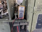
I found some old terminal blocks I had laying around and connected to 12 leads from the stator to it. I then measured between them all again, and the only windings that are showing close to a short is T9 - T12. I show an open circuits between all the leads and ground.

IMG_0573.JPG

Started the unit and it bogged down again. Disconnected P5/J5 and it ran fine.

So it would appear I have a short winding in the main stator. :(
 
Top