• Steel Soldiers now has a few new forums, read more about it at: New Munitions Forums!

  • Microsoft MSN, Live, Hotmail, Outlook email users may not be receiving emails. We are working to resolve this issue. Please add support@steelsoldiers.com to your trusted contacts.

303M HydraMatic rebuild

rustystud

Well-known member
9,266
2,962
113
Location
Woodinville, Washington
It was raining like "a cow pissing on a flat rock" today so I decided to install the front and rear servos .
During this I realized I had forgotten to remove the check ball and spring in the modified front servo I'm going to use. I posted about this in post #121 . I showed what needed to be modified on the front servo to fit our 303M transmission. I also went back and corrected some information I posted last summer.
I also found out about the "A" and "B" MWO modifications. If I had just read my manuals instead of skim read them I would have found this out. Instead I just skim over stuff I think I already know, like "yeah yeah I know this blah blah blah" . Turns out I really need to "read" the manuals and supplementals I own !
The A and B MWO is converting the 302M transmission into a 303M unit.
When the first HydraMatics where installed in the M135's they thought they could get away with just using three clutch plates in the front drum assembly ! The "civilian cars" had five clutch plates at this time !!!!
What were they thinking !!!!
They also replaced the rear servo unit with one that dumped fluid faster giving a faster band apply.
Now back to my install of the servo's.
First off you need to install the rear "discharge tube" into the back of the case. You will need to make sure it is fully engaged. It will be a snug fit.
Second, partially install the front servo, leaving a gap between the servo and main case of about 1/4" . That will allow you to fit the rear servo in since it needs to go into the connecting tube between the two servos and also fit into the rear band socket.
Make sure the front servo tube is fitting securely into the front pump and the servo apply pin is fitting into the front band socket. Also the "discharge tube to the back of the case needs to be installed into the front servo at this time.
Thirdly, install the rear servo. Making sure it is fitting into the front servo connecting tube and the rear band socket. Install all the bolts and slowly turn them down until all assemblies are fully seated. Then torque them down, 28 to 33 ft Ibs .
 

Attachments

USMC 00-08

Well-known member
1,182
179
63
Location
Skiatook, OK
Well Tom "Wolboldt" has not been seen since September 24, 2017 .
So, "USMC 00-08" if you can get his phone number that would be great.
Working on getting his phone number. Will report back.

I decided to install the front and rear servos .
During this I realized I had forgotten to remove the check ball and spring in the modified front servo I'm going to use. I posted about this in post #121 . I showed what needed to be modified on the front servo to fit our 303M transmission. I also went back and corrected some information I posted last summer.
I also found out about the "A" and "B" MWO modifications. If I had just read my manuals instead of skim read them I would have found this out. Instead I just skim over stuff I think I already know, like "yeah yeah I know this blah blah blah" . Turns out I really need to "read" the manuals and supplementals I own !
The A and B MWO is converting the 302M transmission into a 303M unit.
When the first HydraMatics where installed in the M135's they thought they could get away with just using three clutch plates in the front drum assembly ! The "civilian cars" had five clutch plates at this time !!!!
What were they thinking !!!!
They also replaced the rear servo unit with one that dumped fluid faster giving a faster band apply.
Ok. I had mentioned in post #104 that my transmission had the A and B MWO. So I have the 303M but would still need to modify the front servo like you have at the point it ever needs rebuilt?
 
Last edited:

rustystud

Well-known member
9,266
2,962
113
Location
Woodinville, Washington
Working on getting his phone number. Will report back.


Ok. I had mentioned in post #104 that my transmission had the A and B MWO. So I have the 303M but would still need to modify the front servo like you have at the point it ever needs rebuilt?
You don't need to modify the front servo if you don't want too. The stock servo works just fine.
The modified servo I'm using will give me engine braking abilities and it has a greater surface area on the piston for more holding power.
 

m1010plowboy

Well-known member
Steel Soldiers Supporter
3,908
2,712
83
Location
Edmonton, Canada
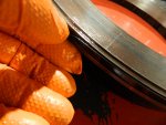
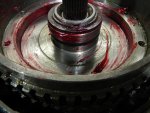
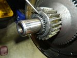
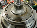
Spent the day cleaning up the "output shaft bearing retainer" and apply piston.
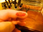
I also ran my left index finger through the wire wheel on my grinder :oops: !!!
I took off about 1-1/4" of skin. Lots of blood, no fun at all.
Need to pay more attention when cleaning parts on the wire wheel !
We could have sat on youtube all day and not get injured. Having ambition can be hazardous. One ambitious fella I worked with was using a wire wheel to paint prep our trailer when he let out a scream. If those wires aren't grabbing a finger and pulling it in, they are coming off at high speeds and lodging in various body parts. In this case, the crouched position with the legs spread open allowed that tiny wire to penetrate the coveralls and jab itself right into the swimmer holding sac. That's right, .....while we're waiting for your skin to grow back, we can picture that poor fella in Emergency.....announcing that he had a wire lodged in his purse.

For those chiming in that have not used a wire wheel on a grinder, even after decades of experience, they can still get you. Here are a few tips but my first tip is, Get Rich and pay someone to run your grinders. https://www.ccohs.ca/oshanswers/safety_haz/abrasive_wheels/safeuse2.html
 

rustystud

Well-known member
9,266
2,962
113
Location
Woodinville, Washington
We could have sat on youtube all day and not get injured. Having ambition can be hazardous. One ambitious fella I worked with was using a wire wheel to paint prep our trailer when he let out a scream. If those wires aren't grabbing a finger and pulling it in, they are coming off at high speeds and lodging in various body parts. In this case, the crouched position with the legs spread open allowed that tiny wire to penetrate the coveralls and jab itself right into the swimmer holding sac. That's right, .....while we're waiting for your skin to grow back, we can picture that poor fella in Emergency.....announcing that he had a wire lodged in his purse.

For those chiming in that have not used a wire wheel on a grinder, even after decades of experience, they can still get you. Here are a few tips but my first tip is, Get Rich and pay someone to run your grinders. https://www.ccohs.ca/oshanswers/safety_haz/abrasive_wheels/safeuse2.html
The worst one I had was one got stuck in my eye. I was wearing safety googles too ! Somehow it wound itself around the googles air holes and got me.

031.JPG033.JPG
All I can say is thank the good LORD for lidocaine ointment !
 

rustystud

Well-known member
9,266
2,962
113
Location
Woodinville, Washington
Today I finished with the servos and started with the reduction unit.
If you follow the book and have the special adjusting tools it is pretty straight forward. If you don't have the adjusting tools it gets harder.

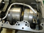
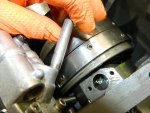
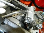
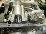
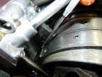
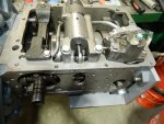
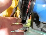
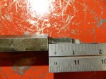
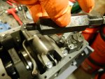
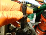
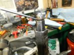
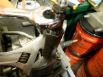
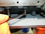
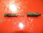
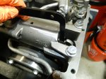
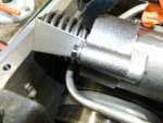
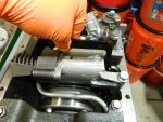
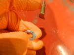
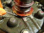
The first thing you do is adjust the tool. You need 1/8" of the adjusting nut exposed. First photo. Then install it in the top of the servo after removing the pipe plug. After hand tightening the tool use a wrench to hold the main body of the tool and using another wrench tighten five turns the adjusting nut on the tool Then you tighten the band adjusting bolt until that little washer on top of the tool just starts to loosen. Then you just tighten the band adjusting bolt jam nut and your done for the front servo.
006.JPG007.JPG008.JPG011.JPG
009.JPG010.JPG
The book goes into detail about the "band adjusting rod" which I just throw away. Their usually broken and really don't do anything.
Now if you don't have the adjuster tool you can still adjust the front band by engine RPM which is actually the best way to adjust the front band. Just get the band adjustment close before buttoning up the transmission. Apply air pressure to the front servo and if it grabs the drum so that you cannot turn it, call it good. That's close enough for the RPM adjustment to work.
Some might ask how adjusting the front band by RPM's is best, well you never know how the band will grab the drum. Sometimes newer bands will grab really fast so they need less adjustment. Other times older bands will need more adjustment to hold. The RPM way is the only way to truly adjust for any situation. I'll post it for those who want to know how to do it later. Too much writing. Maybe I'll just cut and paste it.

Now onto the rear servo adjustment.
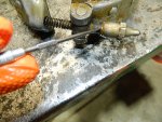
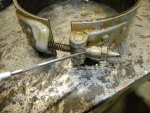
If your lucky, the "rear servo actuating lever" is working correctly. Using the checking gauge adjust the band adjusting screw until there is a gap of about 3/8" to 1/2" between the gauge and the servo actuating lever. Than just apply and release air pressure to the apply passage (where the valve body bolts too) . This action of applying and releasing air pressure will cause the automatic band adjuster to tighten the band. Then just finish up once the automatic band adjuster stops by tightening the band adjuster bolt until you have a gap of 1/8" between the gauge and servo apply rod.
Now if you don't have the rear servo gauge, just apply air pressure until the automatic band stops and call it good.
 

Attachments

rustystud

Well-known member
9,266
2,962
113
Location
Woodinville, Washington
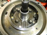
The rear shaft bearing support is the only part I use grade 8 bolts on. I also use "Nordlock" washers on the bolts. This part is the one part you do NOT want coming loose !

022.JPG019.JPG
After the support is bolted down and torqued (33 ft Ibs to 38 ft Ibs. ) it's time to install the piston. First off install the rubber seal to the support and then the piston being careful to not "roll" the seals. Make sure the seals are fully seated into the gooves. Use lots of assembly lube too.
Once the seals are in, place the piston on top of the guide studs ( do not attempt to install the piston into the guide studs yet) . Using your fingers, gently run them around the outer rim of the piston pushing the seal in. Use both hands. You will feel the piston start to drop and touch the guide rods. Now slowly turn the piston (without putting any pressure on it ! ) until it locks into the guide rods. Now if you chamfered the piston holes like I told you too this should happen without any problem. It should now drop into it's bore. Push down on the piston to make sure it is fully seated.
023.JPG025.JPG
I usually test the piston at this time. First, I put "ViseGrip" pliers on the housing to prevent the piston from flying out of it's bore. Then I gently apply air pressure to the oil supply passage and watch the piston move. There are four oil passages on the outside face of the piston to lubricate it when it comes into contact with the "driven cone" . Those passages will blow air out so don't worry about that. Just make sure the piston raises up.
027.JPG
 

rustystud

Well-known member
9,266
2,962
113
Location
Woodinville, Washington
Well I'm totally pissed off today !!!!
I had finished the reduction unit build-up and decided to test the pistons with full air pressure.
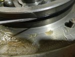
I blew out the rubber seal on the 13" piston !!!! and it cracked the output bearing support housing !!!
AH !!!!!!!!!!!!!!!!!!!!!!!!!!!!!!!!!!!!!!!!!!!!!!!!!!!!!!!!!!!!!!!!!!!!!!!!!!!!!!!!!!!!!!!!!!!!!!!!!!!!!! 😭

I have spare housings thankfully, but I only have one rubber seal left and it's a used one too.
This build is starting to get to me. I'm dealing with 50 to 70 year old parts with almost nothing new available. Reusing old sealing rings and rubber seals which it appears can just rip to shreds at a moment's notice. Still haven't found anyone able to make up that "wave spring" so I'm forced to reuse that too.
When I worked on these units back in the 70's , parts where still available. I could just have all new parts ordered up and put on my work bench and rebuild a unit with no hassle.
I do have a lead on a NOS rubber seal, but it will cost me $100.00 . Just one seal.
This has not been a good week.
My brother is dying in a hospital in Florida, my best friend from high school is moving to Montana, and my body is giving out. Now this stupid seal is causing me grief.

Oh well enough of that pity party. On the bright side, that seal blew out on my work bench and not in the truck ! That would have been really bad.
I just need to get back to work.
I still have three more 303M transmissions to tear-down. Maybe one of them has some good parts this time.
 
Last edited:

rustystud

Well-known member
9,266
2,962
113
Location
Woodinville, Washington
I got everything tore back down, and ordered two seals from "Fatsco" . They had eight in stock. Just that one seal. Strange how things work out. The seals will be here by next Thursday, so in the meantime I will start tearing down more 303M transmissions. I still have some information to share tonight.
 

rustystud

Well-known member
9,266
2,962
113
Location
Woodinville, Washington
Here's some pictures from before the seal decided to blow up.

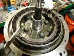
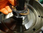
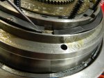
001.JPG After the large reduction piston is installed, install this thrustwasher and the two seal rings.
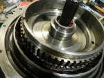
002.JPG Then comes the "Direct clutch Drum" assembly or High speed clutch. You can install the piston in there before installing it on the transmission if you so desire. It's pretty straight forward since the edges are all tapered. The piston seals slide easily over them.
003.JPG Then install the bronze thrustwasher and steel backing washer and then the snap ring.

004.JPG

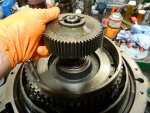
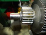
Now install the "clutch hub" and "sun gear" . Installing the snap ring can be a bit of a bear. So lay the transmission on it's side and using a pry bar on the rear clutch assembly in the main body pry back the whole assembly towards the rear.
025.JPG
Then you can install the snap ring. I went and bought "Full Round" snap rings that use two prong pliers.
They are the best rings for this application.
026.JPG This ring does not interfere with any other components which is why the other rings are still used in the transmission.
Now you can install the bronze clutches and steel plates.

The book says to use 7 bronze and 6 steel plates, but I have found that leaves an extremely large 1/4" gap in the housing where in modern transmissions the gap is usually no larger than .090" at most.
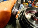
So I went and installed 8 bronze and 7 steel clutch plates. That leaves me a gap of about .060" .
I might just go with 7 bronze and 7 steel plates. Putting the extra steel plate against the piston.
I'm not going to race this transmission, so the gap doesn't need to be extra tight, but it does need to be tight enough to prevent slippage during shift transfers. I believe this is one of the main resaons for this clutch failure. I have torn down 303M transmissions that had this clutch literally burnt up. The bronze plating actually melted ! That kind of heat only comes from slipping under load. I truly believe these clutches burnt up due to the extremely large gap that the piston was trying to overcome.
Remember, this clutch pack is applied during "high gear" (which actually means direct drive) . So, the transmission was in low reduction and trying to go into high gear when this shift problem acurd.
The truck was more than likely under load and the driver was trying to get out of low range without slowing down and due to the large (factory) gap in the clutch pack the clutches could not grab fast enough to prevent the slippage. By eliminating this large gap and the time it takes to overcome this gap
you can have a much quicker and less slipping shift. Better for everyone ! Especially the transmission !


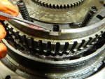
027.JPG Use one of the bolts to help guide the steel plates. The square notch goes on the bolt. Once all the clutch plates are installed you need to install the eight springs. They go in the round notches. It is important to keep the steel plates straight and inline with each other. Use a screwdriver to accomplish this.

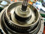
Install the "reduction drive cone" over the "reduction clutch drum" and then install the wave spring and washer. The wave spring ends need to be down. Shown here.
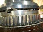
021.JPG Install the eight piston return springs and then your ready to install the "internal gear" .This part is tricky as the eight return springs need to go into there respective holes in the internal gear bottom. Also the internal gear has a "Notch" that aligns with a cutout in the drum assembly.011.JPG013.JPG
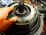
After all the springs are in their proper place you can install the eight bolts. I went and used "NordLocks" here also, as the bending straps are totally worn out. Slowly tighten the bolts down until all are touching down. Then torque then to 28 to 33 ft Ibs. Use a pry bar on one of the bolts to hold the drum assembly from spinning.
 

Attachments

Last edited:

rustystud

Well-known member
9,266
2,962
113
Location
Woodinville, Washington
Spent the day cleaning up the outer rear reduction housing on my last teardown.
Tomorrow after helping the wife deal with a shipping issue, (hate dealing with Fed Ex) I'll start on another teardown. Three more 303M's to go and then two civilian HydraMatics.
Maybe by next summer I'll be able to work on those Allison 1000's I have.
 

1944mb

Active member
419
110
43
Location
Big Timber, MT
Spent the day cleaning up the outer rear reduction housing on my last teardown.
Tomorrow after helping the wife deal with a shipping issue, (hate dealing with Fed Ex) I'll start on another teardown. Three more 303M's to go and then two civilian HydraMatics.
Maybe by next summer I'll be able to work on those Allison 1000's I have.
Whats your plans for all these 303's when you are done?
 

rustystud

Well-known member
9,266
2,962
113
Location
Woodinville, Washington
Whats your plans for all these 303's when you are done?
I plan on rebuilding one more 303M with some special modifications just to do it. Then, I don't know. I might rebuild one for "plowboy" just for grins and giggles. I really want to get back on rebuilding the Allison 1000 transmissions I have. One of them is going into my M35A2 Deuce.
By the way. Did that servo reach you ? You should have received it by now.
 
Top
AdBlock Detected

We get it, advertisements are annoying!

Sure, ad-blocking software does a great job at blocking ads, but it also blocks useful features of our website like our supporting vendors. Their ads help keep Steel Soldiers going. Please consider disabling your ad blockers for the site. Thanks!

I've Disabled AdBlock
No Thanks