• Steel Soldiers now has a few new forums, read more about it at: New Munitions Forums!

  • Microsoft MSN, Live, Hotmail, Outlook email users may not be receiving emails. We are working to resolve this issue. Please add support@steelsoldiers.com to your trusted contacts.

M1078A1 "Pandora" Build | 2024-??? | ***Picture Heavy***

Aviator4x4

Well-known member
Steel Soldiers Supporter
145
268
63
Location
NC
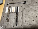
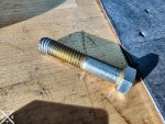
While I'm waiting on parts from Allison, I figured I would tackle the corner bolt issue which was so, so much worse than I thought it was haha. When I removed this shorter, yellow zinc coated bolt... A section of aluminum threads came out with it.
20241230_151956 export.jpg

As seen here, with an original transmission bolt which is ~5-10mm longer. Some eagle eyed members might also notice another issue...
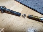
20241230_152038 export.jpg

The bolt in the trans that ripped the threads out is actually an SAE bolt cranked in to an M10x1.5 hole.
20241230_152209 export.jpg

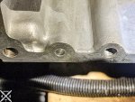
In addition to some higher up threads being broken, the lower threads were all buggered up:
20241230_152418 export copy.jpg

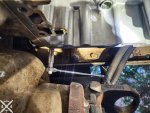
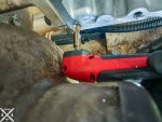
After some internet research, I bought this M10x1.5 Helicoil kit, the shortest 13/32 bit I could find, and the shortest 90* adapter I could find. The 90* adapter was for "impact" but there wasn't much slop so I figured I'd give it a try. Ended up working.
20241230_152926 export.jpg

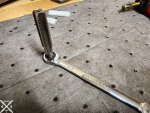
The tap and installation tool were too long so I 3d printed some softjaws, cut them down, and squared the ends to fit snugly in a ratcheting box wrench:
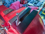
20241230_162835 export.jpg

20241230_172944 export.jpg

20241230_165732 export.jpg

20241230_170127 export.jpg

20241230_172514 export.jpg

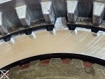
I haven't used too many helicoils before, but seemed to go more or less according to plan. Trying to figure out the best plan for helping those gouges and scrape marks seal... he worst ones are perhaps 1/32" deep or less than 1mm. I think there are two of them, from where someone pried on the aluminum trans block to separate rather than using the jacking ports. Thinking of adding a small amount of RTV on both sides of a new gasket from Allison. Thoughts ? Other recommendations ?
 

aw113sgte

Well-known member
Steel Soldiers Supporter
841
1,319
93
Location
La Crosse, WI
Damn, sorry you had an idiot shove the wrong thing in the wrong hole. Nice work on the fix though!
I would use a little rtv, very little. A little loose piece of rtv can cause all sorts of issues in a trans with all the moving control bits.
 

Aviator4x4

Well-known member
Steel Soldiers Supporter
145
268
63
Location
NC
Damn, sorry you had an idiot shove the wrong thing in the wrong hole. Nice work on the fix though!
I would use a little rtv, very little. A little loose piece of rtv can cause all sorts of issues in a trans with all the moving control bits.
Haha yeah... the seemingly endless rabbit hole of transmission problems with this truck strikes again. Discouraging but I just keep holding on to the vision of what I want to build the truck in to. Hopefully I can achieve it with a lot of luck, little bit of skill, and no experience :LOL:

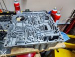
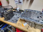
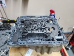
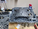
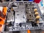
I'm thinking of wetting a fine diamond hone and using that on the gouges to make them flush with the surface, and then putting ~1/16" bead of ultra grey on the trans block gouges. Wait 24+hrs before filling the trans, for sure. After disassembling the entire valve body/control valves, it's not terrible... but I'd also like to not do it again.
 

Aviator4x4

Well-known member
Steel Soldiers Supporter
145
268
63
Location
NC
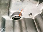
Feeling better about my hypothesis of where the water came from. It rained here yesterday and I could see a waterline/drop on this dry rotted filler seal:

1735614710394.png

Really hope that is the cause. I can't see any other plausible points of ingress; the breather cap on the top of the trans is in good shape, but I'm going to 3d print a little umbrella for it anyway.
 

GeneralDisorder

Well-known member
Steel Soldiers Supporter
2,331
5,794
113
Location
Portland, OR
You can use JB weld to fill the gouges and sand them down. I've even done that on head gasket fire ring mating surfaces on engines. Customer was fully aware of the risk and "only" wanted another year out of it. That was about 7 years ago and it's still running.
 

Aviator4x4

Well-known member
Steel Soldiers Supporter
145
268
63
Location
NC
You can use JB weld to fill the gouges and sand them down. I've even done that on head gasket fire ring mating surfaces on engines. Customer was fully aware of the risk and "only" wanted another year out of it. That was about 7 years ago and it's still running.
Interesting idea. I think I might !

Did you use regular JB weld Cold weld or something more exotic ?
 

Aviator4x4

Well-known member
Steel Soldiers Supporter
145
268
63
Location
NC
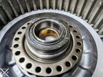
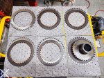
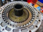
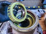
Got the new composite thrustwasher installed, reinstalled the C6 clutchpack in the housing, lined up the snap ring to satisfy my OCD, and got the housing re-installed with 19 new bolts and 1 re-used torqued to 45-55ft-lb.

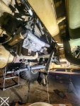
It went surprisingly smooth considering it's basically a 55# overhead press underneath the truck to get the housing back on.

I made sure to thoroughly coat everything in oil as I was re-assembling, which was awesome when it all came dribbling out of the housing when I reinstalled. Oh well. haha.

20241226_174524 export.jpg

20241226_174619 export.jpg

20241226_181239 export.jpg

20250118_155306 export.jpg

20250118_160002 export.jpg

20250118_172552 export.jpg

20250118_181421 export.jpg
 

Aviator4x4

Well-known member
Steel Soldiers Supporter
145
268
63
Location
NC
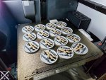
Sidequest: Several friends have pitched in to help work on the truck, or been especially helpful (Allison dealer, for one) so I made this little plastic token as a Thank You. It's double sided with the Aviator4x4 logo on the other side. Plan is to update the design as the truck gets painted or gets the habitat put on.

With how much this build is costing, I might need to have a bake sale that includes one with each cupcake though :LOL: :LOL: :LOL:

20250117_182144 export.jpg
 
Last edited:

Aviator4x4

Well-known member
Steel Soldiers Supporter
145
268
63
Location
NC
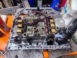
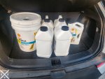
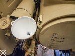
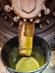
This past weekend I got the valve body/pan back on the truck (what a freaking exercise in tedium that is !) and did my best to flush out all the water contaminated fluid. I pulled the return from the cooler and let that pump ~7gal of fluid into 2x buckets before the fluid turned a more normal oil color. I ended up 3D printing a funnel that fit exactly in the filler hole to make my life 5% easier, but still was a lot of fluids to add !

20250201_180307 export.jpg
Before adding any fluid, just letting it drain and getting it pointed towards the bucket.

20250201_171323 export.jpg

20250201_184829 export.jpg

20250201_202645 export.jpg
 

Aviator4x4

Well-known member
Steel Soldiers Supporter
145
268
63
Location
NC
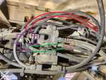
I ended up having to idle the truck with my airlines open/venting after the manual hydraulic conversion... I traced the lines; the smaller 1/4" line for cab air suspension goes to the wet tank on the side, but the bigger 3/8" air line for the (now removed) Air/Hydraulic Pump Unit goes to the rear brake anti-compounding valve on my 2002 A1 (A0.5) ... curious difference from the A0, although would make sense if that port was only active when parking brake was on/parking air was removed.

I'm going to try and to get a better picture of what it was attached to. It says "Special" on the band. Perhaps a one way check valve ?
1738682704544.png

There is another 90* compression fitting on the bottom of "Special" (circled in green, AHPU Air in red)
1738682937973.png

I was hoping it would be as easy as @Ronmar makes it to be in his AOP air supply control valve removal YouTube video but... of course not :LOL:

Going to be difficult to securely get a wrench the 90* fitting to put a pipe plug in with the rats nest of airlines...
 

Ronmar

Well-known member
4,134
7,939
113
Location
Port angeles wa
Yea they did it different on the later trucks. From some other pics I have seen i think it is the same type remote control valve as I removed in my A0 video. i think they put it back there for simplicity as primary and secondary tank air are already combined back there with a 2way check valve(near drivers frame rail) to feed the anti-compound valve. so all they had to do to provide AOP air was T off of that line to feed the remote valve that is controlled by park air…

you will have to follow the source line to where it T’s and remove that T. Then trace the park air control line back to where it T’s off of the line feeding the anti-compound . that park air line may also run to the air brake protection valve out on the passenger side of that crossmember(black plastic valve body seen in your pics) that feeds the rear glad-hands. Then of course remove the remote control valve and the line up to the AOP… or you can simply cap that line that runs to the AOP…
 

Aviator4x4

Well-known member
Steel Soldiers Supporter
145
268
63
Location
NC
Been a couple months since I last updated, but I have been busy ! With work, life, and the truck. I got the air brakes sorted out and successfully test drove it 2 weeks ago ! For anyone else reading this thinking of, or having removed, the AOP and manifold on an A1:

1744411491091.png
1. Remove the Red line - Feeds air to the manifold -> AOP (Can be traced from the manifold back)
2. Remove the Green line - Provides air to the purple cross
3. Remove the Purple Cross & replace with NPT plug - This is a one way check valve that prevents AOP from working when parking brake isn't applied
4. Replace brown T fitting with 90* fitting (See pictures below)

I used Loctite 545 Pneumatic/Hydraulic Pipe Thread Sealant and Loctite 7649 Klean N’ Prime: Activator on the fittings I installed. No air leaks yet (pretty thoroughly sprayed with warm soapy water).

It was a slow, tedious, process to fit wrenches up in that rats nest and I found having different brands of the same size with different angles was helpful.

20250208_155638 export.jpg

20250223_164728 export.jpg
Anti compounding valve with NPT plug where the one way check valve was.


20250223_164712 export.jpg
Shiny 90* elbow where a T fitting was previously

After all that, I attached my cab air suspension to the outlet on the wet tank that used to feed the manifold and added a 1/4x1/4 ball valve so I could turn it off... kind of. Needs work on a way to bleed it once pressurized but it is something and if the air suspension totally fails, I can at least keep air in the wet tank.

20250209_152949 export.jpg

20250223_165010 export.jpg
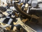
Like any good "30 min job" itll take hours and require a significant tool spiral. Can see the one way valve on the right by needlenose, the T fitting in the middle, and in the yellow box is a reducing adapter the one way valve was attached to.
 

Aviator4x4

Well-known member
Steel Soldiers Supporter
145
268
63
Location
NC
And for an actually interesting/exciting update, I started on what I thought was going to be one of my first projects, regearing the hubs with EcoHubs !

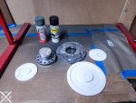
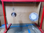
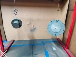
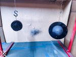
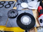
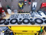
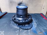
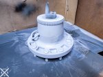
I 3D printed some blockoff plates since all 4 would be the same, red scotchbrite sanded them (unfortunately in the 14mo of them being in my garage, had some surface rust on some parts), wiped with acetone, then 2 coats of Rust-Oleum Self Etching Primer Matte Dark Green followed by Rust-Oleum Farm & Implement Paint, Low Gloss Black.

20250327_210546 export.jpg

20250327_211456 export.jpg

20250327_211630 export.jpg

20250327_220926 export.jpg

20250328_100100 export.jpg

20250329_114230 export.jpg
 

Aviator4x4

Well-known member
Steel Soldiers Supporter
145
268
63
Location
NC
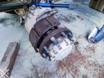
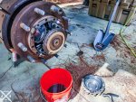
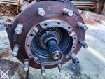
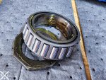
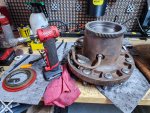
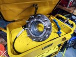
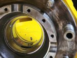
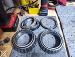
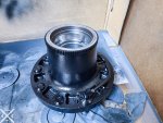
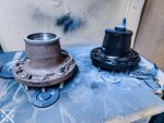
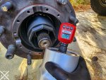
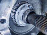
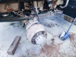
While I was painting those, I also started pulling the hubs. Figured 23yo truck... probably needed some love in the wheel bearings department, but actually looks very recently serviced... unfortunately they packed both the hub oil side AND other side with grease. Which explains the almost glitter waterfall first time I drained the hubs... but seems fine. No scoring or pitting. Can't feel any of the marks on the spindle, bearings, or sleeves in the hubs.

20250402_175006 export.jpg

20250329_115905 export.jpg

20250329_121327 export.jpg

20250329_124523 export.jpg


20250330_162651 export.jpg

20250330_162731 export.jpg
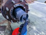
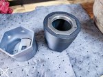
3D printed a 3 7/8" socket extension (and adapter since amazon sent me 6pt instead of 8pt... whatever).
Correct socket: OTC 1913 8 Point Socket, 3-7/8" Opening Size

20250330_133811 export.jpg
8POINT NEEDED ! OTC 1913 8 Point Socket, 3-7/8" Opening Size


20250329_145946 export.jpg
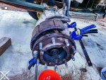
Little bit of mechanical spreading and they came off real nice.

20250330_143411 export.jpg
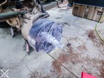
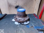
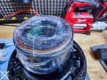
Each of the now exposed spindles got cleaned with WD 40 and then saran wrapped with the brake shoes + a white trash bag to sit for 48hrs before I reinstalled the hubs.

20250329_155845 export.jpg
One corner off...


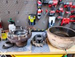
I saran wrapped up the original hubs, labeled them, and put them in long term storage and am sandblasting the brake drums to paint... MTF on that.
 
Last edited:

Aviator4x4

Well-known member
Steel Soldiers Supporter
145
268
63
Location
NC
I keep hearing about "zero mile resets" on FB and other groups... not sure what all that entails, but it's quite possible this truck had one done. There was a 2019 rebuild tag on the transmission, now all 4 corners have new brakes and freshly packed wheel bearings+new looking CTIS & axle seals. Eh. Still going to go over everything to the best of my ability while I have the time/weather/motivation to do so.

20250329_171017 export.jpg
This grease looks WAY too new to be 23yo... I'm guess less than 3yrs. I also drove this truck from TX to NC on this grease, but I did drain/fill the front hubs first and this glitter came out...

20231220_194225 export.jpg

20250329_145512 export.jpg
Which the hub side wheel bearings being packed in that grease explains completely.

20250329_150207 export.jpg
 

Aviator4x4

Well-known member
Steel Soldiers Supporter
145
268
63
Location
NC

Aviator4x4

Well-known member
Steel Soldiers Supporter
145
268
63
Location
NC
Started reinstalling hubs and EcoHubs today !

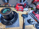
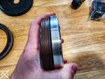
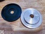
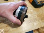
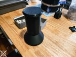
The seal drivers available on Amazon/Napa aren't an exact fit, but the TMs have diagrams of how to make the perfect seal driver. I split the middle and 3D printed some adapters for the commercially available metal ones (after getting $200-400 quotes back for having metal seal drivers made... eh. I'll spend an hour and $5 in plastic).


National Oil Seals RD296 Installation Tool
National RD272 Seal Installation Adapter Plate (For CTIS)
National RD306 Seal Installation Adapter Plate (For axle seal)


These large 9.25" KNIPEX External Snap Ring Pliers were excellent for the rear axles. I didn't pull the shafts, just used the same 3D printed extension on OTC 1913 8 Point Socket, 3-7/8" Opening Size and had no issues.


20250331_215515 export.jpg

20250331_215917 export.jpg
Using the TM drawings, perfect fit for driving in the seals.

20250331_222103 export.jpg
I used Lucas Oil X-Tra Heavy Duty Grease since it's a polyurea grease like the OEM mil stuff. Have heard it's not good to mix lithium and polyurea so no lucas red for this truck ! I'm sure I could have put a lith grease in the hubs since I thoroughly cleaned them, but eh.

20250331_222217 export.jpg

20250331_222439 export.jpg
I could install seals faster than I could install the hubs + EcoHubs lol

20250401_181247 export.jpg
3D printed extension for OTC 1913 8 Point Socket, 3-7/8" Opening Size had zero issues with the 50ft-lb first torquing of the axle nuts.

20250403_211145 export.jpg
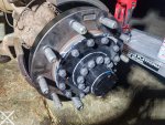
Re-shimmed the axle nuts from hub face per the TM, installed "Delta Locks", then split collar, then direct drive adapter + plate.

20250403_221542 export.jpg
I know, I'm an artist with grey RTV and blue loctite.

20250403_201749 export.jpg
Looks like my truck skipped leg day for 23yrs straight haha.
 

Aviator4x4

Well-known member
Steel Soldiers Supporter
145
268
63
Location
NC
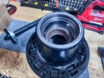
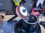
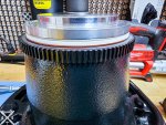
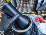
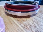
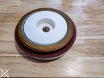
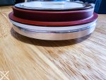
Here are some pictures of the fitment of the commercially available seal drivers. It's close... but almost completely ineffective since the aluminum adapter plates want to drive the seals from their inner rubber parts vs outer metal. They are, however, much more economical than having a fab shop make the seal drivers per the TM. Of course if you have a metal lathe with DRO (or CNC + DRO) that would probably be better still !

Again, here's the ones I adapted. I'll post the files on printables or thingiverse or wherever if there's interest.

For science I also 3D printed a full sized CTIS seal driver and it worked fine, but the 3D printed adapter on the "upside down" aluminum plate drove the seal in much more securely and with fewer whacks.

20250330_110130 export.jpg

20250330_110152 export.jpg

20250330_110349 export.jpg
3D printed plate on the flat side of the aluminum disk. Worked great !

20250330_110407 export.jpg


20250401_095154 export.jpg
3D printed a full size per the TM CTIS seal driver. Worked ok but I preferred the adapted metal one above.

20250403_193109 export.jpg

20250330_110612 export.jpg
Same deal with the hub seal. Not quite a perfect fit.

20250330_110544 export.jpg

20250330_110559 export.jpg
 
Top