• Steel Soldiers now has a few new forums, read more about it at: New Munitions Forums!

  • Microsoft MSN, Live, Hotmail, Outlook email users may not be receiving emails. We are working to resolve this issue. Please add support@steelsoldiers.com to your trusted contacts.

Advice needed - new guy with MEP004A

Back-in-Black

Well-known member
296
277
63
Location
Louisiana
Well, it's gonna be a while before I get to finish this. As soon as the framers are finished what they've started, they're gone. I'm tired of half-assed work and idiots who can't read plans. I spent good money paying an architect to design all this out and these idiots can't seem to read what's on the prints right in front of them. Poor workmanship, no pride in their work, etc. Second contractor I fired. As you may have guessed by this thread, I'm a bit "picky". Some would probably call it "anal". It'll take a bit longer and be a lot of work for me, but damn! I just can't deal with half-arsed work.
 

Mullaney

Well-known member
Steel Soldiers Supporter
Supporting Vendor
7,716
19,766
113
Location
Charlotte NC
Well, it's gonna be a while before I get to finish this. As soon as the framers are finished what they've started, they're gone. I'm tired of half-assed work and idiots who can't read plans. I spent good money paying an architect to design all this out and these idiots can't seem to read what's on the prints right in front of them. Poor workmanship, no pride in their work, etc. Second contractor I fired. As you may have guessed by this thread, I'm a bit "picky". Some would probably call it "anal". It'll take a bit longer and be a lot of work for me, but damn! I just can't deal with half-arsed work.
.
Nobody seems to be able read blueprints these days. Paper (or electronic) plans require somebody to actually READ and then use a ruler. Maybe there are some, but not as many as there was in days go by...

Blueprints don't have a flashy screen and buttons to push, so these days that cuts out most of the younger folks.
 

Back-in-Black

Well-known member
296
277
63
Location
Louisiana
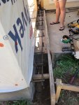
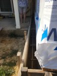
Yeah, first the concrete guy got the forms off by 9". He started the slab at the edge of the existing porches ( front & back). Well, there was a brick wall on that end of the house, and then, behind the bricks was a sheet of 7/16" OSB and a sheet of 1/2" foam board behind that and then the 2x4 stud wall. The concrete actually got poured like that and then it became apparent that the new walls weren't going to line up with the old wall for tie-in. So, I spent the entire Memorial Day weekend adding 9" of concrete to the new slab so the walls would line up. 27 bags of concrete and a crap-load of 5/8" rebar along with 15 gallons of my sweat. Then the framers had to tear down the walls you see in the picture below and move them 9" and extend the front and back walls by 9". This was not the framer's fault though. Then, a few weeks ago the wife had a heart attack when she noticed that the window on the front wall was now not centered on the peak of the gable. It was off by a whole 4-1/2 inches - half of the 9" we extended the wall. She was actually crying about it. Good grief Charlie Brown! So I spent another weekend moving the freaking window frame 4-1/2"!

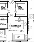
Then, Friday night, I was using the plans to figure out how much tile flooring I was going to need in the bathroom when I noticed that the east wall of the bathroom is drawn much thicker than other walls and is labeled in BIG letters - "2x6 BALLON FRAME WALL". Guess what, that whole wall was built with 2x4s. The roof is built, the shingles are on, the OSB and Tyvec are on the wall and the widows are due in Wed. I sent an email to the architect asking what needs to happen. Still waiting on his reply now.

I'd MUCH rather be working on my MEP-004a!!!!!

20220528_124249.jpg

20220529_174411.jpg

balloon wall.PNG
 

Back-in-Black

Well-known member
296
277
63
Location
Louisiana
Well, the architect said it must be 2x6 AND it must be "balloon" framed. Structural thing. I had to look up Balloon Framing the other night when I found this problem. It simply means that the 2x6 studs in the wall go all the way up - they don't stop at the cap of the wall. They are actually one stud from the floor plate all the way to the roof ?truss? - not sure truss is the right word there. Architect said having the studs stop at the wall cap and then putting separate studs from there up to the roof truss creates a "hinge point" that could "fold" under stress. This wall has a gable in the roof - see pic.

It's the wall with the gable above it that sticks out the furthest to the left in the pic.
20220622_074748.jpg


Broke the bad news to the contractor today. He's coming over in the AM.
 
Last edited:

Abrant23

Active member
Steel Soldiers Supporter
145
186
43
Location
Charleston, SC
Well, the architect said it must be 3x6 AND it must be "balloon" framed. Structural thing. I had to look up Balloon Framing the other night when I found this problem. It simply means that the 2x6 studs in the wall go all the way up - they don't stop at the cap of the wall. They are actually one stud from the floor plate all the way to the roof ?truss? - not sure truss is the right word there. Architect said having the studs stop at the wall cap and then putting separate studs from there up to the roof truss creates a "hinge point" that could "fold" under stress. This wall has a gable in the roof - see pic.

It's the wall with the gable above it that sticks out the furthest to the left in the pic.
View attachment 872806


Broke the bad news to the contractor today. He's coming over in the AM.
Easy peasy, cut the top plate on the 2x4's and sister in 2x6 the full height of the wall. You'll have to order a door with a wider jamb if that's what is framed out there, if its just a window you're golden. Not really a hard fix at all since the sheetrock isn't up yet.

Is the interior ceiling vaulted? If not, then there really isn't a reason for balloon framing here. You can tie the side wall into the ceiling joists at the top plate if it is a flat ceiling
 

msgjd

Well-known member
1,080
3,317
113
Location
upstate ny
.
Nobody seems to be able read blueprints these days. Paper (or electronic) plans require somebody to actually READ and then use a ruler. Maybe there are some, but not as many as there was in days go by...

Blueprints don't have a flashy screen and buttons to push, so these days that cuts out most of the younger folks.
1st day on a 4-story brick building interior gut/reconstruct project, the FNG in his late-20's is standing over the blueprint table, sees that something is off.. The Lead man yells over at him "don't just stand there we gotta get busy and do something ! " The new guy tries to tell the Lead there appears to be some unusual requirements and suggests he should come take a look .. Exasperated, the Lead continues to bang stuff up and look the part of a very busy beaver, mad as hell at the effengee.. At the end of the day the Lead was proud of the progress, which was certainly much more than what the newbie had accomplished .. The next morning the Lead was taken aside by the boss who was with the project engineer. After that, the Lead spent most of the day ripping out everything he had personally done and the following day standing over the prints and starting over.. I wound up with a promotion I wasn't looking for and a position I didn't want to have. But it all ended good.. Some people just need a little push into better things , and some people can or could learn to read prints, but choose not to and pay the price ;)
 
Last edited:

msgjd

Well-known member
1,080
3,317
113
Location
upstate ny
Well, the architect said it must be 2x6 AND it must be "balloon" framed. Structural thing. Architect said having the studs stop at the wall cap and then putting separate studs from there up to the roof truss creates a "hinge point" that could "fold" under stress.
Outside residential walls have to be a minimum of 2x6, but the other stuff is so typical of how different jurisdictions have different opinions/requirements.. Is the Balloon method an actual local requirement , or actually stated in today's IBC (Inter. Building Code) , and not the personal preference/opinion of the architect ? (same applies to inspectors) .. Seen that at times over the decades with some who interject personal preferences into projects, and when challenged, they are unable to produce the actual code to back up their opinion/preference... It does happen. Ask me sometime about an MSHA inspector who was harassing and fining a customer of mine about not performing a certain annual testing requirement. When challenged, he could not and never did produce documentation of its existence, and was never seen in the area again. I question the balloon construction, since that is the easiest type to take down ! .. Remove the siding and give a wall a tug, it hinges perfectly at the base and the whole barn or house or garage falls flat on the ground with a crash.. LOL ... Been on hundreds of new home projects in NY, VT, NH, and MA since the 1980's and none of them were balloon, and some hit by hurricane winds yet didn't budge.. There are ways to mitigate hinge points, and yes, hinging is a real thing builders have to think about
 
Last edited:

Back-in-Black

Well-known member
296
277
63
Location
Louisiana
This is how he explained it in his email reply to me:

The cap at the top of the wall becomes a hinge-point so balloon was needed. Because the studs will now be longer / taller (16ish feet), a 2x4 is not strong enough - hence the 2x6.

Normal here is 2x4. Interior or exterior walls. ALL the other walls, with the exception of the wall where the plumbing vent goes up to the roof are also 2x4 but that one is due to diameter of vent pipe. Had to have 2x6 to fit the vent pipe.

Not really sure I understand why balloon on that one wall. Sure, It has a gable, but so do 2 other walls that are not balloon and not 2x6. NO clue, but I guess that's why I paid an architect LOL.

I had to Google "balloon framing" to even have a clue....
 

peapvp

Well-known member
Steel Soldiers Supporter
1,115
1,235
113
Location
Basehor, KS
Same guys who make the motor controller I've been looking at. What do you guys think? Field 5-50 ohm.


View attachment 851009

View attachment 851010


I am jumping into this thread at a very late stage, but it always amazes me when a member shares the idea of replacing a original exciter unit with an aftermarket unit.
Here, in this particular case the British manufacturer requires a exciter field winding impedance of 5 Ohm to 50 Ohm and sure enough another member will then point to the applicable TM of the Genset and points to the published Resistance / Resistance Range which is usually verified using a VOM or DMM.

So, what's wrong with this picture?

1. A resistance measured with a Volt Ohm Meter / Digital Meter is a DC Resistance

2. A Impedance is the AC resistance of a Resistor / Capacitor / Inductance in an AC Circuit

The TM's refer to DC Resistance, the manufacturer of the after market unit refers to impedance / AC Resistance


An ideal resistance does change with frequency when connected with DC. Impedance is the measure of the nature of opposition of the AC electricity which is created due to inductance and capacitance.
...
Difference Between Resistance and Impedance
ResistanceImpedance
It is used in DC circuits.It is used in AC circuits.


The next time I travel to see Shane and his 005A in Liberty, KS I will take my Impedance Tester with me and report the actual impedance of a 005A exciter winding measured between F1 and F2 with pictures and videos.

One thing in advance,

The result will shock you

Peter
 

Back-in-Black

Well-known member
296
277
63
Location
Louisiana
I agree with you up to a point. You're not wrong but impedance is measured in Henrys, not Ohms. So if the manufacturer lists min. resistance in Ohms, then I'm gonna assume that they're talking DC Ohms as in resistance across (thru) the coil, not impedance. That is my assumption and it was also based on the basis of the specs for what was already there and (at one time) working. Furthermore, if you think about it a bit, impedance is probably not all that important with regards to a VR, where resistance is VERY important: as in - anything less than the minimum listed resistance would probably be seen by the VR as a dead-short and would inevitably "let the magic smoke out" of the VR.

Also, not replacing a factory system. This thing already had an aftermarket, solid state voltage controller (voltage regulator). There's not much left on the whole genset that actually is "factory". I ended up replacing the VR that was on there with a newer version of the same thing. So far, works great.

But yes, I definitely understand your point and it is a very valid point!
 

peapvp

Well-known member
Steel Soldiers Supporter
1,115
1,235
113
Location
Basehor, KS
I agree with you up to a point. You're not wrong but impedance is measured in Henrys, not Ohms. So if the manufacturer lists min. resistance in Ohms, then I'm gonna assume that they're talking DC Ohms as in resistance across (thru) the coil, not impedance. That is my assumption and it was also based on the basis of the specs for what was already there and (at one time) working. Furthermore, if you think about it a bit, impedance is probably not all that important with regards to a VR, where resistance is VERY important: as in - anything less than the minimum listed resistance would probably be seen by the VR as a dead-short and would inevitably "let the magic smoke out" of the VR.

Also, not replacing a factory system. This thing already had an aftermarket, solid state voltage controller (voltage regulator). There's not much left on the whole genset that actually is "factory". I ended up replacing the VR that was on there with a newer version of the same thing. So far, works great.

But yes, I definitely understand your point and it is a very valid point!
I am trying to explain this as simple as possible as I don't want to turn this into EE 104

An impedance is always abbreviated as Z and expressed in Ohm

However, Z is a resistance at a particular Frequency, here we are concerned with Z at 50Hz / 60Hz

Z is usually used for a part like a piece of wire, formed as coil in our case. A wire, as you had pointed out, has always an inductance, a DC Resistance and a capacitance especially when a straight piece of wire is formed into a coil shape.

And this is where the deep black art of analog electronic engineering starts.

When applying a DC into a coil then the Voltage proceeds the current flow at the beginning. After a x amount of time, depending on the Coils DC Resistance and its inductance, The Current and Potential are in sync.

This initial offset of Voltage / Current at the start is what we utilize to excite the stator of the generator.

This creates the field.

The Job of the AC Voltage Regulator is it now to turn the 24 VDC into a AC Voltage of up to 93 VAC which is synced by the AC Voltage Regulator to the actual engine rpm which equates to Frequency.

At this point, the AC Voltage Regulator actually creates a sine wave on F1 / F2 and "see's" the exciter coil as impedance (AC Load) at 50Hz or 60Hz at around 93 VAC for most generators which then produces 208/230 or 240/120 VAC on the generator terminals

This load impedance Z is now a combination of Inductance, DC resistance, Capacitance and Frequency expressed in Ohm

Once we know this impedance we can actually calculate the current flow through the coil which is different then the current flow through the coil with just DC applied.

The actual Z can be much higher or much lower then the plain DC Resistance of the coil

A coil besides having a Z also has a Q which varies with Frequency, but for our case we will leave Q out of the picture.

Peter
 

kayak1

Active member
97
161
33
Location
Maine
Well, the architect said it must be 2x6 AND it must be "balloon" framed. Structural thing. I had to look up Balloon Framing the other night when I found this problem. It simply means that the 2x6 studs in the wall go all the way up - they don't stop at the cap of the wall. They are actually one stud from the floor plate all the way to the roof ?truss? - not sure truss is the right word there. Architect said having the studs stop at the wall cap and then putting separate studs from there up to the roof truss creates a "hinge point" that could "fold" under stress. This wall has a gable in the roof - see pic.

It's the wall with the gable above it that sticks out the furthest to the left in the pic.
View attachment 872806


Broke the bad news to the contractor today. He's coming over in the AM.
In the old day's balloon framing, they put up triple deckers walls and then added the floors.

I don't think that you are doing old-school balloon framing without fire stops. My understanding is that it's not allowed per NFPA.


Back-in-Black

Well-known member
296
277
63
Location
Louisiana
Don't have time to read and digest all of this right this minute but I will - love learning new stuff. And not sure about how all this works but I do know that resistance can be used to "augment???" impedance ? I know that in sound systems you can use resistors in-line with multiple speakers in order to keep the impedance of the chain from getting so low that amp blows transistors. Also, this genset had 2, big, ceramic resistors between the VR and the field coils. One on the main field and one on the Delco alternator field. Maybe your explanation above will fill me in on why this works when it's impedance and resistance. Have wondered about that for a long time.
 

peapvp

Well-known member
Steel Soldiers Supporter
1,115
1,235
113
Location
Basehor, KS
Don't have time to read and digest all of this right this minute but I will - love learning new stuff. And not sure about how all this works but I do know that resistance can be used to "augment???" impedance ? I know that in sound systems you can use resistors in-line with multiple speakers in order to keep the impedance of the chain from getting so low that amp blows transistors. Also, this genset had 2, big, ceramic resistors between the VR and the field coils. One of the main field and one on the Delco alternator field. Maybe your explanation above will fill me in on why this works when it's impedance and resistance. Have wondered about that for a long time.
Yes by adding a resistor you can change Z
That works to a certain extent, you can also add a AC Capacitors to change Z
 

Back-in-Black

Well-known member
296
277
63
Location
Louisiana
In the old day's balloon framing, they put up triple deckers walls and then added the floors.

I don't think that you are doing old-school balloon framing without fire stops. My understanding is that it's not allowed per NFPA.


yes, they rebuilt the wall the other day - I made them add fire blocks.
 

Back-in-Black

Well-known member
296
277
63
Location
Louisiana
I am trying to explain this as simple as possible as I don't want to turn this into EE 104

An impedance is always abbreviated as Z and expressed in Ohm

However, Z is a resistance at a particular Frequency, here we are concerned with Z at 50Hz / 60Hz

Z is usually used for a part like a piece of wire, formed as coil in our case. A wire, as you had pointed out, has always an inductance, a DC Resistance and a capacitance especially when a straight piece of wire is formed into a coil shape.

And this is where the deep black art of analog electronic engineering starts.

When applying a DC into a coil then the Voltage proceeds the current flow at the beginning. After a x amount of time, depending on the Coils DC Resistance and its inductance, The Current and Potential are in sync.

This initial offset of Voltage / Current at the start is what we utilize to excite the stator of the generator.

This creates the field.

The Job of the AC Voltage Regulator is it now to turn the 24 VDC into a AC Voltage of up to 93 VAC which is synced by the AC Voltage Regulator to the actual engine rpm which equates to Frequency.

At this point, the AC Voltage Regulator actually creates a sine wave on F1 / F2 and "see's" the exciter coil as impedance (AC Load) at 50Hz or 60Hz at around 93 VAC for most generators which then produces 208/230 or 240/120 VAC on the generator terminals

This load impedance Z is now a combination of Inductance, DC resistance, Capacitance and Frequency expressed in Ohm

Once we know this impedance we can actually calculate the current flow through the coil which is different then the current flow through the coil with just DC applied.

The actual Z can be much higher or much lower then the plain DC Resistance of the coil

A coil besides having a Z also has a Q which varies with Frequency, but for our case we will leave Q out of the picture.

Peter
Ok, I read this a couple more times. I understand what you're saying - to a point. I know impedance is not really "resistance" and I know it's caused in a coil by the magnetic field. I've read things like "it's a special kind of resistance".

I will be googling it and doing some more reading on it. But not right now! It took me this long to come back and spend a few minutes reading this post a couple more times.


I've basically fired all the contractors on the house because I keep ending up tearing all their crap apart and re-doing it. I got to the point where I asked myself.... 'why the heck am I paying these guys good money and then I have to work twice as much to tear their shortcuts out and rebuild it right?" Just didn't make sense. Maybe I'm just too picky?

Anyway, I really got my hands full. Windows are being installed tomorrow and once that's done, I can really get going on the siding. I also bought the book for electrical that was suggested earlier in this thread by @robertsears1. Been reading that but haven't started wiring yet. I got the trim up at all the corners but the 2 under the front and back porches. Once the windows are in I can trim them and do siding. I did some siding a few weeks ago as a "trial" to kind of get a feel for it and see what sort of problems I would run into. The dang windows have taken 9 weeks to get here!

Here's the little bit of siding I did.

20220717_175503.jpg

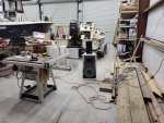
And I have to admit that as it was raining this afternoon when I knocked off work, I didn't work on the home addition, I went out to the shop and played for a few hours. Been collecting sound system parts for a while and I'm pretty much ready to start putting stuff together for a stereo in the shop. Got 4, JBL AM6219/95 speakers. 4, SLS LS6500 speakers, 3, QSC RMX 2450 (2 channel x 450 Watts / channel) amps and various EQs and such. I had hooked up a pair of the JBLs to one of the amps a while back and while they sound pretty good, they are HEAVY in the bass dept and pretty light in the mids and highs. Well, tonight I hooked up 1 JBL and one SLS tonight and WAAAAAAY better! Ought to sound awesome once I get 1 each hung at the ceiling at each corner of the shop. I ordered Speak-ons and XLRs tonight to use wiring it all up. One of the QSCs has a bad channel. Pretty sure it has a bad MOSFET as it starts clipping in that channel at 10dB gain and it heats up VERY fast. Will have to send that in for repair. Also have a couple of Biamp 120 Watt mono amps but they're pretty much toast. Probably won't repair or use them as I think 2,700 Watts is probably enough :LOL: Guess I'll have to "borrow" my manlift again to hang the speakers. Anyway, I wasted the evening playing with that. LOL Oh! And all the gear was free!!!

20220819_225720.jpg

20220819_225738.jpg
 
Last edited:

Gunger

New member
1
1
3
Location
Indiana
Well, got a call as I was walking out to the car. Stay home. Kinda nice, but lucky I had my phone on!

View attachment 847310

You are correct that the springs are there to keep the loovers closed. The loovers need to be closed to help the gen set warm up to 180 degrees running temp, that it so loves to be at.

This is a good diagram of the control assembly. Inside the round part, (item # 23) it is filled with bees wax. Or so I was told about 30 or so years ago. You will not find this diagram in the 004A or 005A books. This was taken from the 006A book. I have never taken one completely apart, as it is a a pluck and chuck item.

There is a piston that is activated when the temp of the coolant causes the bees wax to expand. The piston is pushed out, forcing the loover vanes to open, and when every thing works right, keep the gen set happy at 180 more or less. The best way to test it is naturally, start the set cold, and wait to see if it opens up. If you are not going to put the box back on the gen set, then it will not work. The set is designed to run with all doors closed. So do not run the set for hours and hours without the box. A while to test things is OK. The fan draws the cooling air through the set. When the loovers are closed, doors closed, it heats up fairly fast. There is a test procedure in the -34 to test the control assy. Simply heat up some water, and put the control assy. in it, and see if it moves. I can not remember the whole procedure off the top of my head, so do read it if you want to try testing that way.

We almost always just tapped out a gasket for the mating of the housing and radiator. Its a simple one that takes only a few min to tap out.

Pay attention to reassembly. Look at the TM for the procedure. Its easy to get it out of wack, and the loovers don't open wide enough, or too wide. When its all back together, you should be able to push the manual control handle down, the loovers open, and then when you release the handle, they snap closed with a real nice "Clap". And you do NOT want your fingers in there when they close. And the handle can also bite you! The system is designed to allow you to "force" the loovers open, to prevent over heating if the control assy. is bad. There is/was a rope on a hook there, to hold it open, when need be. With a bit of patience, you can get the set to run about at normal temp, by changing the length of the rope. You can also just tighten up the pivot bolt on the handle assy, and then the system is blocked/locked open.
I have a mep-005a that I’m working on.
That lower water neck part that bolts to the bottom of the radiator #21 in that parts diagram picture is almost all the way rotted off on mine.
Is that part available still?

How important is it for the louvers on the front of the radiator to work like there suppose to?
 
Top
AdBlock Detected

We get it, advertisements are annoying!

Sure, ad-blocking software does a great job at blocking ads, but it also blocks useful features of our website like our supporting vendors. Their ads help keep Steel Soldiers going. Please consider disabling your ad blockers for the site. Thanks!

I've Disabled AdBlock
No Thanks