Following up on the schematics.
It appears the M1078A1 and M939A2 wiring harnesses routed a few items differently at what appears to be the (M1078A1's P110) connector to the CTIS ECU.
Since
@GeneralDisorder has suggested the Dana Spicer ECU's do not connect across J1939 and we can connect to our Dana Spicer using J1708; I am thinking IF using the M939A2 CTIS ECU in our M1078A1 we need to disconnect 'G'.
note: The plaza Arduino CTIS ECU does not connect to the J1939 circuit at all, ('G', 'W', 'X').
M939A2 DIFFERENCES
1— no diagnostic connections listed;
2— speed signals routed through 'Y' and 'K';
3— pressure switch 'B' also used, routed through 'L';
4— additional ground routed through 'V';
5— 'a', 'N', 'U', 'M' and 'A' not used.
CONFLICTS
The M939A2 CTIS ECU uses — M1078A1 uses:
'G' for the Control Switch 'A' — the M1078A1 routes control switch 'A' to ground through 'F' and uses 'G' for J1939 (+);
note: if you follow the M1078A1 J1939 (+) wire it does connect to R13 and R12.
'M' for the Wrecker Only Ground — the M1078A1 routes ground through 'F' and uses 'M' for optional power;
Should be OKAY?
The M939A2 CTIS ECU uses — M1078A1 uses:
'W' for the Control Switch 'B' — the M1078A1 routes control switch 'B' to ground through 'F' and uses 'W' for J1939 (shield);
'b' for the Pressure Transducer 'A' — the M1078A1 routes pressure transducer 'A' to common through 'j' and uses 'b' for power;
'j' for the Pressure Transducer 'B' — the M1078A1 routes pressure transducer 'B' to power through 'b' and uses 'j' for common;
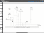
M939A2 schematic
View attachment 913437
M1078A1 <18500 schematic
View attachment 913438
As I fried the last of my 120ohm resistors I'll have to await the arrival replacements, to see if disconnecting 'G' may allow using the M939A2 CTIS ECU in our M1078A1 unit without conflicting with the J1939 system and causing a fault in the ABS system—


