• Steel Soldiers now has a few new forums, read more about it at: New Munitions Forums!

  • Microsoft MSN, Live, Hotmail, Outlook email users may not be receiving emails. We are working to resolve this issue. Please add support@steelsoldiers.com to your trusted contacts.

My new 1992 M998 Avenger

springer1981

Well-known member
844
1,150
93
Location
Maine
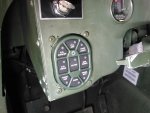
I picked up one of the electronic light switches to replace the old style lever switch. The lever switch worked fine and I had complaints about it except the space it took up. The levers stick out and one of the future mods I would like to make is moving the steering column in about 2 inches. This would put the directional lever very close to the light switch levers and likely interfere.

The electronic switch says it is a direct replacement for the mechanical switch however there are tabs that need to be removed from the dash. The tabs are used to space the original switch so that is just stick out of the dash. The new switch is much short and doesn't use the tab. I used a cutoff wheel and made quick work of the tabs.

The picture shows the tabs and the red line show where I cut. If I ever wanted to put the original switch back in (4) 3/4" spacers would work to set the correct depth.
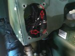
switch.jpg switch1.jpg


I purchased a used steering column on the auction site. I'm going to disassemble it and cut 2 inches out of the shaft and weld it back together. Then I'm going to cut 2 inches out of the housing right in front of the turn signal mount and weld it back together. This will allow me to move the steering wheel about 2 inches closer to the dash giving me a little more breathing room.
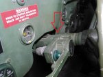
switch2.jpg

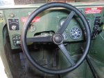
I installed the later style A2 steering wheel. It is a little thicker and has a slightly better feel to it. It is still just a hard plastic wheel and doesn't offer much grip. If the steering column mod works out I will wrap the new wheel with either a vulcanizing rubber or leather to add a little grip and cushion.
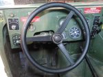
Steering.jpg

While investigating modifying the steering column I closely checked out all the steering column mounts to see if there is any other way than actually cutting it down. There really isn't an alternative option but I did see a curved slot on both side mount. After checking it out I realized the steering column can be raised and lowered giving it a "tilt" option.

How to-
There is a bolt under the steering column that clamps the mounting bracket around the column. It's in plain site as soon as you look under the steering column.
There are also 2 bolts at the bottom of steering column, 1 on each side.
Loosen those 3 bolts and you should be able to move the steering column up and down about 3" of travel. Pick the spot you like the most and tighten the 3 bolts.
 

springer1981

Well-known member
844
1,150
93
Location
Maine
Everything Ive read about those switches lately revolves around them being notorious for starting fires.

I like the high zoot look but after seeing several pics of crispy buttons, I'm wary of them.
That may be but how many of the thousands and thousands that were made actually failed? The next question would be why did they fail? Where they designed for trucks that use LED lights and people retrofitting them overloaded them?

I converted all my lights to LED and that should be a reduced load. I still have my original switch should I ever need it. I guess I'll find out how long it lasts.
 

Milcommoguy

Well-known member
Supporting Vendor
1,713
2,279
113
Location
Rosamond, CA
Springer you make a good point with the led thing. I wonder if that might be the connection to the failures? Is there's a notice to this upgrade?

Sure they look to be the cats meow and yes I wanted one too. They do draw a few micro-amps when off, and that's no big deal. Add to the mix and match of old filament bulbs and / or LED's then what about pulling a trailer? (motorpool Sgt. hook me up with that LED only trailer) If it is load related then somebody missed the boat. It should have been designed to at least equal the old contact switching set-up... But as it goes with HMMWV's IMO, too much high tech electrical for a switch that's been proven in all type of rigs, for over 60 years by teens to old farts like me. Don't get me going on the controller box, HAHA

Not to say there not the coolest, till the smoke comes out. CAMO
 

springer1981

Well-known member
844
1,150
93
Location
Maine
Springer you make a good point with the led thing. I wonder if that might be the connection to the failures? Is there's a notice to this upgrade?

Sure they look to be the cats meow and yes I wanted one too. They do draw a few micro-amps when off, and that's no big deal. Add to the mix and match of old filament bulbs and / or LED's then what about pulling a trailer? (motorpool Sgt. hook me up with that LED only trailer) If it is load related then somebody missed the boat. It should have been designed to at least equal the old contact switching set-up... But as it goes with HMMWV's IMO, too much high tech electrical for a switch that's been proven in all type of rigs, for over 60 years by teens to old farts like me. Don't get me going on the controller box, HAHA

Not to say there not the coolest, till the smoke comes out. CAMO
For me it is the depth of the switch that is important. As for what causes them to burn out, I wonder if they had the same problems when the vehicles were in service? Once they get into the public's hand and backup lights, license plate lights, fog lights, markers on the roof etc. are added then all bets are off.

I have no idea what causes it or if it is even widespread problem. In my case it will only be used for stock lights that were all converted to LED's. I'll see how it goes.
 

juanprado

Well-known member
Steel Soldiers Supporter
5,638
2,956
113
Location
Metairie/La (N'awlins)
There are at least 2 manufacturers. Newest ones are narton and wider than the old ones. Made to fit hmmwv with no mods. Pics on my build thread.
 

springer1981

Well-known member
844
1,150
93
Location
Maine
As previously mentioned I would like to shorten my steering column to move the steering wheel forward as much as possible. I bought one to experiment with. First task was to take it apart. Pulled the seals at each end to inspect how it was assembled. after digging at it with a pick and cleaning some of the grease out of it I found a ring clip in each end however they are captive and I couldn't see a way to take them out. After taking a closer look I see there is a very heavy spring that holds the ring clip captive. No way I am taking that apart without making some special tool to compress the spring and remove the clip. That is a project for another day.

Side note, the light switch didn't burn up yet.
 

springer1981

Well-known member
844
1,150
93
Location
Maine
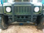
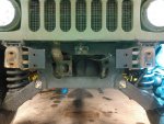
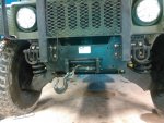
Moving on to the winch install. My truck has the Luverne brush guard. My goal was to mount the winch and keep the brush guard. I know they are not intended to "bolt on" with each other. So there will be some required modifications.
winchbefore.jpg

When I bought the winch one of the hydraulic lines was not mounted on it. It was included but was off. As mentioned in a previous post the valve was damaged as well. With the valve fixed and mounted it was time to put the other line on. Of course it was the wrong line. The top line goes up from the valve body and wraps around the solenoids. The bottom line goes under the motor and up around the back of the motor and then over the top. I had 2 bottom lines and no top line. It isn't easy finding the correct line so I had to make due with what I had. I removed the bottom line and mounted the top line pointed down. Then I bent it to about a 45 degree along the motor and routed it up the back just like the bottom line. It will work for now and I will keep looking for the right line.
winchlines.jpg

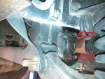
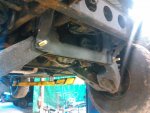
The first thing is removing the lower control arm pivot bolts in the front and reversing them. They also need to be a little longer. The passenger side bolt is pretty easy. Remove nut and use new bolt to follow the old bolt as you pound it out. It moved pretty easy and was a relative breeze to change. The drivers side bolt however is blocked by the brake caliper. I pulled the 2 pins and lifted the caliper up without removing it from the brake rotor. Then replaced the bolt as I did the other. Set the caliper back in place and replaced the pins. It was simple and made it so I didn't have to mess with the pads. I had a friend helping to hold it out of the way. It is definitely a 2 man job.

The red arrows point to the caliper pins, 7mm allen.
winchcaliper.jpg

Here are the 2 bolts in place.
winchbolts.jpg

Next it was time to install the winch mounting brackets. Pretty straight forward.
winchbrackets.jpg

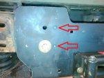
The brackets have 2 holes but the winch has 4. With the Luverne brush guard brackets I needed to use the inner set of holes.
The brackets are setup to use the outer set of holes. I set the winch in place and used the outer set of holes and a bolt on each side to hold it in place while I drilled them. Pilot hole first then finish size. Arrows point to holes to be drilled.
winchdrill.jpg

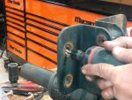
The Luverne mounts needed to be modified to line up the the new holes and the mounts on the outside of the frame (left side in picture above). We marked where the holes needed to be wider or taller and used a die grinder to hog them out.
winchluvholes.jpg

With everything set in place loose we put the brush guard on and tightened it all up.
winchafter.jpg
 
Last edited:

springer1981

Well-known member
844
1,150
93
Location
Maine
Much easier to move the seat back...
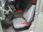
The seat is not going back any farther than it is now. With the Avenger it is a hard top and wall behind the seat. There is absolutely no more room to go back with the seat.

Arrow #1 Seat hits the support. Arrow #2 Seat hits solid non removable back wall. Arrow #3, the Avenger has this shelf that extends all the way across the back wall, behind the seats. I have already cut it and bent it back, behind the driver seat, for the maximum amount of room to move the seat back until it hit at arrow #1 and 2.

seat4.jpg

The only place left to gain a little room is moving the steering wheel forward. I can move it about 1.5-2".
 
Last edited:

Retiredwarhorses

Well-known member
Steel Soldiers Supporter
4,414
4,209
113
Location
Brentwood, Calif
The seat is not going back any farther than it is now. With the Avenger it is a hard top and wall behind the seat. There is absolutely no more room to go back with the seat.

Arrow #1 Seat hits the support. Arrow #2 Seat hits solid non removable back wall. Arrow #3, the Avenger has this shelf that extends all the way across the back wall, behind the seats. I have already cut it and bent it back, behind the driver seat, for the maximum amount of room to move the seat back until it hit at arrow #1 and 2.

View attachment 758936

The only place left to gain a little room is moving the steering wheel forward. I can move it about 1.5-2".
ahh, that’s right...
 

springer1981

Well-known member
844
1,150
93
Location
Maine
Perhaps get rid of that steering wheel and get the new style...makes a huge difference IMO.
Please explain "new style". I have installed the A2 steering wheel and it's shape, set back and diameter are all the same as the original steering wheel. It is however thicker than the original and that actually costs about 1/4" clearance. Is there some other steering wheel that isn't set back as much?

Steering.jpg
 

Retiredwarhorses

Well-known member
Steel Soldiers Supporter
4,414
4,209
113
Location
Brentwood, Calif
Please explain "new style". I have installed the A2 steering wheel and it's shape, set back and diameter are all the same as the original steering wheel. It is however thicker than the original and that actually costs about 1/4" clearance. Is there some other steering wheel that isn't set back as much?

View attachment 759011
You are correct, they are the same, but the thicker wheel just seems to give the impression of easier control ability then the old thin one.
 

springer1981

Well-known member
844
1,150
93
Location
Maine
You are correct, they are the same, but the thicker wheel just seems to give the impression of easier control ability then the old thin one.
In general the feel of the A2 wheel is much improved over the original. However the issue is the distance between the seat and the wheel is made for a young man in the army that runs 10 miles a day and weighs in at 160lbs. I am not that man. I'd like more breathing room and the only way I see that happening is moving the wheel forward.
 

springer1981

Well-known member
844
1,150
93
Location
Maine
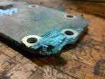
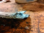
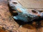
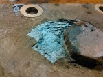
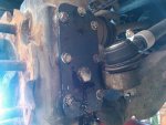
One of the gear covers on the rear hub was corroded to the point I was concerned it would fail and lose the gear oil. This could obviously cause a catastrophic failure. I had a new cover I have been meaning to change out. Today we pulled the wheel and replaced the cover. Here are some pictures of how badly it was corroded.

cover1.jpg cover2.jpg cover3.jpg cover4.jpg cover5.jpg
 

springer1981

Well-known member
844
1,150
93
Location
Maine
While I had it on the lift I also changed out the bolts I used on the winch mount. I thought the original bolts were not going to be long enough and replaced the with 6" bolts. Today I put the original bolts back in and used the original nuts, removing the lock washers I used. I still don't believe the lock washers would ever have been a problem but I didn't like the extra inch of thread sticking out.

winchbolts.jpg
 

springer1981

Well-known member
844
1,150
93
Location
Maine
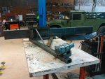
I also started working on a front bumper. I want it to match the rear Air Lift bumper in style but be made specifically for the front. It will work with the Mile Marker winch and Luverne brush guard. I don't care for the huge bumpers that stick out a foot and have all kinds of crap attached. This will mount up tight to the winch but will be bent forward in front of the tires for clearance. It will have the air lift shackle mounts on the ends as well.

But before I get ahead of myself I must first bend it. The plan is to use a sand bending technique. It's not going to be easy, I'm using the same 2" x 8" x 1/4" steel the rear bumper is made out of. Today I built most of the bending jig. When it's all done I want it to look like it could have been part of the original truck.

FB.jpg
 
Last edited:

Bulldogger

Well-known member
Steel Soldiers Supporter
1,331
594
113
Location
Quantico VA
While I had it on the lift I also changed out the bolts I used on the winch mount. I thought the original bolts were not going to be long enough and replaced the with 6" bolts. Today I put the original bolts back in and used the original nuts, removing the lock washers I used. I still don't believe the lock washers would ever have been a problem but I didn't like the extra inch of thread sticking out.
View attachment 760161
How on earth could that get that bad? It looks like galvanic corrosion, or acid corrosion, not rust...

Definitely good that you took care of it. Terrible sight to behold.

BDGR
 

Milcommoguy

Well-known member
Supporting Vendor
1,713
2,279
113
Location
Rosamond, CA
Those covers crap up that way all the time. Mixed metals, salts spray from the road or ocean, beach head maneuvers. Thirty years later you can poke a stick through them.

Another thing to look for / change, CAMO
 
Top
AdBlock Detected

We get it, advertisements are annoying!

Sure, ad-blocking software does a great job at blocking ads, but it also blocks useful features of our website like our supporting vendors. Their ads help keep Steel Soldiers going. Please consider disabling your ad blockers for the site. Thanks!

I've Disabled AdBlock
No Thanks