• Steel Soldiers now has a few new forums, read more about it at: New Munitions Forums!

  • Microsoft MSN, Live, Hotmail, Outlook email users may not be receiving emails. We are working to resolve this issue. Please add support@steelsoldiers.com to your trusted contacts.

My new 1992 M998 Avenger

springer1981

Well-known member
844
1,150
93
Location
Maine
Besides making more room with the steering column and seat mods, my plans for this year are 4L80 as mentioned above. Vic-3 Lite communications for driver/passenger intercom. And a custom install AC system.
 

springer1981

Well-known member
844
1,150
93
Location
Maine
Did you tilt the HMMWV steering column all the up first to see if that helped. They can go quite a bit up and down.
Yes but no amount of tilting makes any more room. There is no other way to make additional room. I will be welding everything back together in the next couple of days as well as modifying the seat. I will be posting updates as I go.
 

springer1981

Well-known member
844
1,150
93
Location
Maine
When I left off with this thread almost 2 years ago last thing I was doing was looking for tires and wheels to move away from the stock Mud tires and 16.5" wheels. I found a good deal on a set of 5 H2 wheels and tires. They had like new BFG 37x12.5x17 A/T All Terrain tires mounted and ready to go. The centers had already been opened up for some other truck so they fit right on. The overall offset moves the tire edge out about 1". I will add a picture later. At some point I will paint them black so they kind of disappear and look more stock but the silver doesn't bother me.
 

springer1981

Well-known member
844
1,150
93
Location
Maine
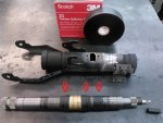
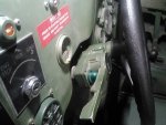
The stock steering column had shrink tubing on each end of the brass horn contactor and where the wire for the horn goes into the steering shaft (3 red arrows). I used Vulcanizing rubber tape instead of the shrink tubing. If you haven't used this stuff I highly recommend you get a roll. I use it for lots of stuff, it is way better than any electrical tape. You simply cut a piece off and stretch it to activate it. Then wrap it around whatever you want. It doesn't use adhesive, it bonds to itself.

You can see the shaft and the column are welded back together. The mount is also welded back on the column.

Steering2.jpg
 

springer1981

Well-known member
844
1,150
93
Location
Maine
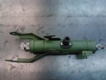
Here is the finished and assembled column. Overall length is 2" shorter than stock. The directional mount is moved 1" forward on the column to clear the dash on the shortened column. Obviously there is a performance gain from the reduced overall weight LOL

Steering3.jpg
 

springer1981

Well-known member
844
1,150
93
Location
Maine
Why not see if a Ford Escort steering column fits your needs. I believe the Escort column is what H1 models use.
The H1 column collapses in a crash.
You brought up an interesting concern regarding collapsing steering columns in HMMWV's. So from what I can tell, the H1 does not use a Ford Escort steering column. It does use a similar steering column as the HMMWV with the exception that it is fitted with a more consumer like directional system and a key type ignition switch.

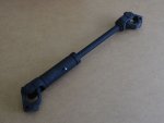
The H1 and the HMMWV use a similar intermediate shaft that does incorporate a collapsing shaft in the event of a crash.

Picture 1 is the H1, picture 2 is the M998

H1shaft.jpg

HMMWVshaft.jpg
 

springer1981

Well-known member
844
1,150
93
Location
Maine
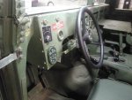
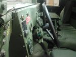
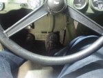
Got the seals in today for the steering column and finished it. The install went pretty smooth. Turns out 2" shorter and moving the directional mount 1" is just about perfect. There is plenty of hand room around the wheel and pretty much has full travel up and down for adjustment. The horn didn't work so I replaced the horn button also and it fixed it. In the last picture you can see I actually have room between me and the steering wheel now. I could have lost 50 lbs but this was easier LOL.

steering8.jpg

steering7.jpg

steering6.jpg

steering5.jpg
 

springer1981

Well-known member
844
1,150
93
Location
Maine
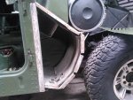
Moving on to the next project, the passenger side front fender has some minor damage. It could have been fixed with a little bondo but who wants that? So tonight I removing the fender. First I started drilling the rivets. Not as much fun as it sounds and takes a lot longer than you would thing. The drill bit slides off center, you don't know how deep to go, just not a lot of fun. I switched to shallow drilling the rivet and then using a good flat screwdriver and a hammer to knock the rest of the rivet head off. It worked better than just drilling it. Then I wondered if I could just knock the heads off with the screwdriver and hammer without any drilling. It worked like a charm and was fast. Had the fender off in no time. A couple of rivets from the inside hidden by the footwell insulation through me for a couple minutes until I found them.

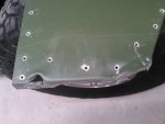
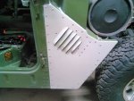
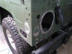
Here's the damaged fender
fender1.jpg

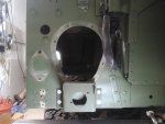
Here's with the fender removed and the rivets cleaned up

fender2.jpg

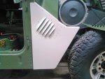
Here's the new panel set in place. I have to paint it first. Then I'll drill a few of the rivet holes to line it up. Use a body sealer adhesive and put it on. The drill and rivet the rest in place.
fender3.jpg
 

springer1981

Well-known member
844
1,150
93
Location
Maine
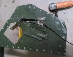
In order to use the old fender as a drill template I cut off anything that wasn't flat. I used a cut off wheel on a grinder and it made quick work of it.

fender3a.jpg


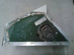
Then I took the template and matched up vent mount holes and a couple of the predrilled rivet holes as best I could. Tightened the vent screws and drilled out all the remaining hole. Any holes that didn't match up perfectly had to be fudged a little but only after carefully considering the repercussions.

fender3b.jpg
 

springer1981

Well-known member
844
1,150
93
Location
Maine
I painted the back side first. Then cleaned off the old body sealer. I used a paintable sealer from the local hardware store. Then riveted it back together. I have a nice air "POP" rivet gun that's worth it's weight in gold. Found it on epay years ago. I happen to have a couple rivets kicking around as well. It went back together pretty good and nearly everything lined up well.

fender4.jpg

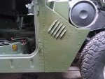
After it was all sealed and riveted I sanded it and put a coat of paint on.

fender5.jpg

In this picture the paint is still wet so it looks a little glossy but it will dry a perfect match. I have to paint the rivets on the inside still and then reassemble the vent but overall I consider this done.

fender6.jpg
 

springer1981

Well-known member
844
1,150
93
Location
Maine
During the disassembly the rubber air duct fell out. After investigating it is obviously new and was just kind of stuffed up in cavity. Also a metal rod about 8" long fell out with it. It took me a few minutes but I figured out it was part of the rubber air duct. It's missing the 16 plastic push clips but I located them online and ordered them. Time to put it back together right.

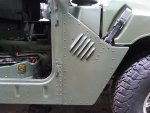
Here is the last picture with the paint dry and a new hood latch installed. New rubber bumpers on the way, the originals are badly dry rotted.

fender7.jpg
 

springer1981

Well-known member
844
1,150
93
Location
Maine
I wanted to install a Vic-3 Lite and didn't want to go with high mount radio tray. So I took my tray and decided to remove the bottom and use it for the mount. I cut the mounts off at the bend and turned it around and placed it upright. Drilled a couple of new mounting holes and bolted it back together and it fit perfect. After locating the Vic-3 boxes and adding 2 holes to mount them, I painted it.

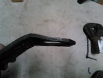
In the first picture you can see the typical radio try. I removed the handset mounts since I will not be using them.
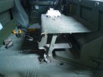
radio1.jpg

You can see the bottom shelf in its new mounting location. I only had to add the 2 mounting holes between the Vic-3 and the crew station. The other holes were existing.
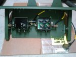
radio2.jpg

I mounted the control box as close to the drive as possible and mount the dual crew station towards the middle so both the driver and passenger have pretty easy access to their volume control. I will be adding a cup holder on each side of the top shelf towards the dash.
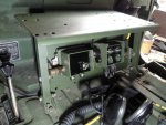
radio3.jpg

Here's a side view. The top shelf gives a nice protective overhang to the radios. I kept the wiring as clean as possible.
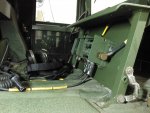
radio4.jpg

Here's the back side where you can see the wiring. The power connector is sitting on top of a hole in the where a power wire would have been run. Since I don't plan on having any radio gear, I'm going to get a mating power connector and mount it in the hole to the floor. This way I won't have any additional wires or need a radio tray. I'll need a radio tray for parts to get the right connector. If anyone has one kicking around with the power plugs let me know.
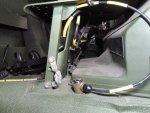
radio5.jpg
 

springer1981

Well-known member
844
1,150
93
Location
Maine
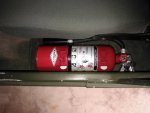
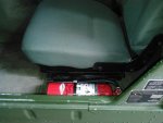
Today's project was a pretty simple one. I found the correct fire extinguisher mount for the seat upgrade I have. I've been looking for a fire extinguisher and checked the ones hanging up at my work. Turns out they were a direct fit. I looked them up online and bought one. It's a Amerex B500 5lb. Cost about $50 shipped. I removed the wall mount loop and it dropped right in although the loop would not have effected it. There are 2 flats machined in to the top and it set right in the slot perfectly.

I will say it's a tight fit overall and will not be super quick to remove but I'd rather have it if I need one than not have one at all.

FireEx1.jpg


FireEx2.jpg
 

springer1981

Well-known member
844
1,150
93
Location
Maine
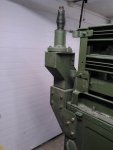
Mounted the offset antenna base. I was missing a couple of parts and found them on epay. Touched up the paint and painted the bolts so it all blends in nicely.

antenna1.jpg
 

springer1981

Well-known member
844
1,150
93
Location
Maine
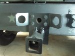
Previous owner put a class 3 hitch on it and since I will probably never tow anything with it I wanted to put the pintle hitch back on. I removed the class 3 and when I went to mount the pintle I found the safety chain plate was bent up. It looks like it did its job. I'll have to find a replacement before I put it back together.

pintle1.jpg

pintle2.jpg
 

springer1981

Well-known member
844
1,150
93
Location
Maine
I replaced the lights a couple of years ago. That that time I knew they needed more work. The tail light buckets and rear side marker light buckets are almost 30 years old and were cracked, worn and brittle. At the same time I also wanted to add reverse lights. The reflectors are also in bad shape. The lens were bouncing around and the trim was dented etc. I removed everything and will clean it all up before reassembling. The tail light buckets are held in with an unusual type of rivet. I'll have to source them before reassembling.

corner.jpg

I mounted the backup light centered with the tail light. With the Rhino Spare tire carrier, it is what worked best on that side. This side is matched.

backup1.jpg
 
Top