• Steel Soldiers now has a few new forums, read more about it at: New Munitions Forums!

  • Microsoft MSN, Live, Hotmail, Outlook email users may not be receiving emails. We are working to resolve this issue. Please add support@steelsoldiers.com to your trusted contacts.

My new 1992 M998 Avenger

springer1981

Well-known member
844
1,150
93
Location
Maine
In a previous post about the ignition switch I mentioned I might try to upgrade it for increased current capability (more AMPS). During my locking steering column modification I cut open the old Chinese key switch ignition and found the contact plate was burnt and melted. This was partially a result of the brass material used not to mention the thickness.

In the new ignition switch the contact plate is made out of solid copper and not brass. This is a bonus however the contacts in the plastic cap are merely bent over copper and the wires get soldered to the tab sticking out. In higher current situation relying on just solder to hold is not good. Screw or crimp terminals would be much better because it is physically held in place unlike solder that is more like gluing it in place. Also the switch insulation appears to be plastic but may have some thermal qualities to it.

My goal would be to build a replacement for the contacts, insulation and contact plate. Using a thermal fiber insulation, thicker contact plate, increased contact area and screw terminals it would significantly improve current handling capability of the entire switch. So I ordered some .042 copper plate, copper rivets, copper screw contacts and thermal fiber insulation.

switch5.jpg


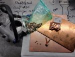
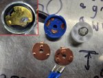
I don't have the insulation yet but today I started with the contact plate. In the upper left corner you can see the brass contact plate with the burnt and melted contact. On the bottom there are 2 copper contact plates, the one on the left is .030 copper with dimple contacts pressed into the copper. It's the original contact plate for the blue switch you see in the middle. The copper contact plate on the bottom right is the one I built. I cut it out of .042 copper plate then located and drilled for the rivets. Because the rivets have a lot more contact area I had to adjust the location and trim one edge so the paths don't overlap when turning the switch. The dimple contact has a very small point of contact vs the large flat rivet. I'm still waiting for the thermal fiber but I will post updates when I make the new cap. I've never made a switch before but if some kid in China can do it, so can I.

switch6.jpg
 

TOBASH

Father, Surgeon, Cantankerous Grouch
Steel Soldiers Supporter
Supporting Vendor
3,578
3,488
113
Location
Brooklyn, NY
In a previous post about the ignition switch I mentioned I might try to upgrade it for increased current capability (more AMPS). During my locking steering column modification I cut open the old Chinese key switch ignition and found the contact plate was burnt and melted. This was partially a result of the brass material used not to mention the thickness.

In the new ignition switch the contact plate is made out of solid copper and not brass. This is a bonus however the contacts in the plastic cap are merely bent over copper and the wires get soldered to the tab sticking out. In higher current situation relying on just solder to hold is not good. Screw or crimp terminals would be much better because it is physically held in place unlike solder that is more like gluing it in place. Also the switch insulation appears to be plastic but may have some thermal qualities to it.

My goal would be to build a replacement for the contacts, insulation and contact plate. Using a thermal fiber insulation, thicker contact plate, increased contact area and screw terminals it would significantly improve current handling capability of the entire switch. So I ordered some .042 copper plate, copper rivets, copper screw contacts and thermal fiber insulation.

View attachment 864240


I don't have the insulation yet but today I started with the contact plate. In the upper left corner you can see the brass contact plate with the burnt and melted contact. On the bottom there are 2 copper contact plates, the one on the left is .030 copper with dimple contacts pressed into the copper. It's the original contact plate for the blue switch you see in the middle. The copper contact plate on the bottom right is the one I built. I cut it out of .042 copper plate then located and drilled for the rivets. Because the rivets have a lot more contact area I had to adjust the location and trim one edge so the paths don't overlap when turning the switch. The dimple contact has a very small point of contact vs the large flat rivet. I'm still waiting for the thermal fiber but I will post updates when I make the new cap. I've never made a switch before but if some kid in China can do it, so can I.

View attachment 864242
Great work. Why not use a Dremel to round off the rivets? Mark the center area and then just use a drimel to gently take off excess material surrounding the contact area. Simple and fast and easy for someone with your skill set.
 

springer1981

Well-known member
844
1,150
93
Location
Maine
Great work. Why not use a Dremel to round off the rivets? Mark the center area and then just use a dremel to gently take off excess material surrounding the contact area. Simple and fast and easy for someone with your skill set.
I'm not sure what you mean. I don't want to round off the rivets. I want maximum contact area and making them smaller reduces the contact area. I
 

TOBASH

Father, Surgeon, Cantankerous Grouch
Steel Soldiers Supporter
Supporting Vendor
3,578
3,488
113
Location
Brooklyn, NY
I'm not sure what you mean. I don't want to round off the rivets. I want maximum contact area and making them smaller reduces the contact area. I
That’s not really the way electrical contacts on this type of device typically work. If you have a long-flat contact next to another long-flat contact, they can unintentionally weld themselves to each other. To prevent that and to help more carefully direct the electricity path, there is usually a pointed surface that sticks up beyond the flat surface. Gently rounding off the rivets would be the way to go. Usually, two different substances are utilized, one hard and one soft, in order to prevent wear and to prevent electrical arcing causing welding and adhesion. By focusing the electricity, it also helps the electrical connection bypass any small amounts of corrosion from oxidation With the pointed surface also mechanically damaging that oxidation to allow for electrical contact.

Brass screws similar to those found in windup clocks substituted for those rivets would be robust and rounded and would diminish the risk of welding.
 
  • Like
Reactions: OBX

springer1981

Well-known member
844
1,150
93
Location
Maine
I made the switch mount and it works but I have to tuck the switch in tighter to the column. I think I can get another 1/8" - 3/16" clearance. This is only required on mine because I shortened the steering column 2", on a stock column it wouldn't be a problem. I ordered a newer style directional switch that will give me much more clearance and possibly auto canceling turn signals.

switch7.jpg

switch8.jpg
 
Last edited:

TOBASH

Father, Surgeon, Cantankerous Grouch
Steel Soldiers Supporter
Supporting Vendor
3,578
3,488
113
Location
Brooklyn, NY
I’ve been involved in more design and more construction when you’ll ever know, architectural, machine and human, however I won’t bother to go into my credentials. I also won’t bother to read any more of your posts. You’re obviously too smart for me.

Good luck with that.

Oh, by the way Mr. Steering column…. I found this in an old post from 2017 (one of many on several forums besides the several H1 vehicles with the words Ford Escort splashed on the steering column)… but hey, you know more than the rest of us and you feel you need to justify your incorrect statements with rudeness and ignorance.D8A1CB1D-A8E1-493F-99CE-E63EF3EC6FE6.png
 
Last edited:

springer1981

Well-known member
844
1,150
93
Location
Maine
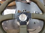
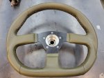
A couple of years ago I bought a steering wheel and adapter for the humvee. I didn't like the look of the adapter and mounts or the horn setup and I put it on the shelf. After mounting the new ignition switch and steering column lock it was time to revisit the steering wheel.

I took the original green plastic steering wheel and cut the 3 spokes and kept the hub. Then cut the plastic away and removed the 3 left over steel spoke nubs. This left me with the splined steel hub from the center.

Steering1.jpg

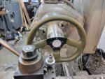
Then I took a piece of Aluminum and turned a flange that centered the new steering wheel.

Steering2.jpg

Then it was time to match the inside dimensions to the old steering wheel so I can use the original horn and retaining ring. I also bored it so I can press the steel hub in.

Steering3.jpg

I finished the outside and pressed in the hub. Then drilled and tapped the bolt pattern for the steering wheel. I plan to paint the adapter I made green and paint the top of the steering wheel and screws you see below flat black.

Steering4.jpg

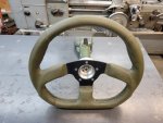
Here is it on a spare steering column. Once I have it all painted and mounted in my truck I will post the end results.

Steering5.jpg
 
Last edited:

springer1981

Well-known member
844
1,150
93
Location
Maine
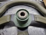
Here's the back of the adapter after it was painted and mounted to the steering wheel.

Steering6.jpg

The back is relieved for the steering column. Here it is in place.

Steering7.jpg

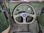
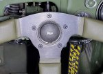
Here's the finished product. Horn mounted in place, connected and works! The "D" shaped wheel definitely improves entry and exit. I'm very happy with the outcome.

Steering8.jpg

Horn.jpg
 
Last edited:

springer1981

Well-known member
844
1,150
93
Location
Maine
So how did you mount the original hub to the aluminum piece that you made? Looks amazing. Is it the same distance from you as the stock wheel? I don’t want mine any closer.
The steel hub was left with a rough surface and pressed into the aluminum adapter. About .001-.0015 press fit. I was going to put two 1/4x20 socket head screws in each side but after pressing in the hub, it was not needed.

The new steering wheel is flatter so I mounted it flush with the top of the adapter. It's the same distance as the original steering wheel. I could have mounted it anywhere along the adapter. The adapter is about 2" long, same as the original steering wheel hub.

I shortened my steering column 2" to move the wheel further away also.
 

springer1981

Well-known member
844
1,150
93
Location
Maine
Pop Rivets. Our trucks have thousands of Pop Rivets. I never knew how many different types of Pop Rivets there are until I started working on my truck. I bought a bag of rivets thinking they would cover most of the rivets on my truck. Not even close. Since that first bag of rivets I have probably bought 15 or 20 different types of rivets.

Just rebuilding my tailgate I think I have bought 5 or 6 different rivets, 3 different types. But most of them are still pretty much just Pop Rivets. That is until you get to the tailgate hinges. These are "Pop" rivet on steroids. Since one of my hinges was bent and I was rebuilding the tailgate anyway I removed the hinges. I had to remove the bent hinge to fix it. On the tail gate it was impossible to straighten the hinge because it would just damage the tailgate.

These rivets are Huck BOM rivets. BOM stands for Blind, Over-sized and Mechanically Locked. They are no ordinary rivet, strong as WELDS. That's a bold statement they claim, for a Pop Rivet. It took me a couple of weeks to find the correct rivets because I didn't need 250 for $300 x 2 types. I just needed 6 of each type. I managed to find 25 of each type for a total of $50. Seems simple enough BUT WAIT there's MORE. The rivet gun to put them in starts at $1600.

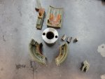
This is a picture of a BOM rivet. The red arrow points to a tapper on the top of the rivet. Here's how it works. That tapper fits the rivet tool. When the rivet mandrel is pulled, the back side of the rivet collapses forming something like a screw head. Then when the mandrel stop crushing the back side the rivet tool overcomes the metal on top (red arrow) and compresses it around the mandrel locking it in place. The last step is the mandrel breaks off. The force to do this is a LOT. Did I forget to mention the rivet gun is hydraulic and connects to a hydraulic pump? What you see beside the rivet is a tool I made. Not exactly sure how I'm going to use it yet. The hole in the center is made to match the tapper on the rivet.

BOM1.jpg

Here's the other side of that tool. You can see the rivet in the tapper. The idea is to apply enough force to collapse the back of the rivet and then compress the metal head around the mandrel.

BOM2.jpg

Since I wasn't sure how hard it would be to remove the tool after compressing the rivet I put wrench flats on it so I could turn it to break it free if needed. This was my first attempt and it work OK. I think I need to tighten up the tapper on my tool and make it shallower to force the compression further down. However I will say, you can't pull my 2 test pieces apart with just that 1 rivet holding them. You can't pry them apart, you can't rotate them. They do not move. I could probably use this as is but I think I can make it better.

BOM3.jpg

This is the back side. In my opinion, strong as a weld. More to follow on Rivet Tool 2.0

BOM4.jpg
 
Last edited:

springer1981

Well-known member
844
1,150
93
Location
Maine
I had some tailgates that had hinges bolted to the body. This may be why.
I came across that in the TM's. Looks like they might have changed them or retrofitted them. I think they also have spacers inside the tailgate for the top 3 holes on each side for the bolts.
 

springer1981

Well-known member
844
1,150
93
Location
Maine
I removed my test rivet I did the other day because I needed the hinge to work with. Also it gave me a chance to see just how well the rivet worked. I tried to pound the rivet mandrel through with a hammer and punch and it would not move. I cut the top off and I was then able to remove it. Overall it worked as intended.

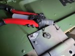
I found a heavy duty pop rivet tool at Harbor Freight for $25. The rivet mandrels are not long enough to go through the tool I made and the tool nosepiece and be gripped by the jaws. I removed the nosepiece and I had to modify tool I made to remove the outside rim. After the modifications I tried my first rivet and it worked perfectly.

BOM5.jpg

I had to do 12 rivets and it was not an easy task but they are done. Now waiting for paint to dry.

BOM6.jpg
 

Mullaney

Well-known member
Steel Soldiers Supporter
Supporting Vendor
7,716
19,766
113
Location
Charlotte NC
Today was a little slow so I built this handy battery carrier. I'm going to test it this weekend.

View attachment 865494
.
Interesting... My battery carrier is a really large fan belt (twice as wide as a belt on my Cummins for example) Rubber between the battery posts gives me more flexible with different battery sizes.

GUESSING you must have some sort of insulator between the posts and the metal carrying handle?
 
Top