• Steel Soldiers now has a few new forums, read more about it at: New Munitions Forums!

  • Microsoft MSN, Live, Hotmail, Outlook email users may not be receiving emails. We are working to resolve this issue. Please add support@steelsoldiers.com to your trusted contacts.

303M HydraMatic rebuild

rustystud

Well-known member
9,280
2,987
113
Location
Woodinville, Washington
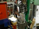
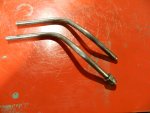
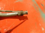
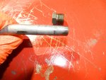
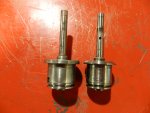
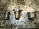
I've been receiving a little interest in the "front servo" upgrade I posted about. I did say it is a drop in installation, but I need to clarify it a bit. You will need to cut off the pipe nut which normally threads into the servo. The later model servos did not use this nut. They just had a straight pipe go into the servo.
This is a picture of the two pipes.
006.JPG
So just cut off the flare end and your Golden !
001.JPG002.JPG

You will also need to plug this hole with a 1/8" pipe plug. Use a 21/64" drill bit and drill down 1/2" . Then tap out with a 1/8" NPT tap.

001.JPG003.JPGI installed a stainless steel 1/8" plug here.

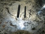
The last thing you need to do is remove the check ball and spring shown here.
011.JPG013.JPG
 
Last edited:

rustystud

Well-known member
9,280
2,987
113
Location
Woodinville, Washington
Had a talk with the gasket maker "Gardico" and we're looking at two to three weeks out. Went to the machine shop also. He is extremely backed-up and is looking at maybe three weeks before he can even start on my projects.
I have a few things left to tear down and clean-up. One being the rear oil pump. Actually, I have seven pumps to tear down and clean-up. Also, about seven rear servo's and three front servo's.
I'll post about the rear pump, and anything that pops up during the servo clean-ups.
I still have three more complete civilian HydraMatics to tear down also. I'll post anything interesting.
Other than that, I probably will not be posting much for about a month.
 

rustystud

Well-known member
9,280
2,987
113
Location
Woodinville, Washington
I've been getting ready to visit "plowboy" up in Canada and part of getting ready was rebuilding a Front servo unit for Dave.
I noticed something I never thought to check before. The 303M front servo has a smaller piston then the later (1953 on) civilian HydraMatics . This piston in the civilian models gives you an extra 0.120" larger piston. That's translates into more band holding power. So going to this later style servo not only gives you the "engine braking" ability in third gear, but also gives you better holding power in all the gears with the front band applied.
Also, the 303M piston rod has a hole drilled through it for no reason I can think of. The civilian model has a stronger solid rod.

001.JPG
 

DUUANE

Active member
409
128
43
Location
Qualicum Beach BC
Well you should get some credit as you sold me one of those 303M transmissions. :)
Now If I could only find a few more. Do you have any leads ?
I know where a couple of trucks are.. but seems like they are pretty much the usual runners with no brakes, or no reverse or both. Ill ask Rick at Milspec Hydraulics if he has any spares he can let go.
 

DUUANE

Active member
409
128
43
Location
Qualicum Beach BC
I spoke with Rick this morning. No dice on the cores. He came under the same pressures i did and dumped 90% of his stock. Realestate is so insane here. It makes it almost impossible to run a business out of a rental yard. Constant turnover.
He is always finding more gear. When he gets something he will call me.
 

rustystud

Well-known member
9,280
2,987
113
Location
Woodinville, Washington
I spoke with Rick this morning. No dice on the cores. He came under the same pressures i did and dumped 90% of his stock. Realestate is so insane here. It makes it almost impossible to run a business out of a rental yard. Constant turnover.
He is always finding more gear. When he gets something he will call me.
Well thanks for asking around. I will be visiting "plowboy" in late August. Should see something along the way.
 

rustystud

Well-known member
9,280
2,987
113
Location
Woodinville, Washington
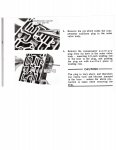
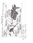
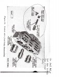
Started cleaning up some valve-bodies today. No special tricks or anything except to watch out for the
"compensator auxiliary plug" . This plug sits behind a pin that must be removed to access the valve. This valve is always stuck ! It is not mentioned in the "TM 9-8025-2" manual. This picture is from another rebuild manual I have. If you can get your valve to move in its bore, then just leave it alone. It is so easy to "cock" this valve and score the bore it's not worth the risk trying to remove it. I also never remove the "exhaust body valve" or the "throttle valve cutoff valve" . Both have plugs that need to be pressed in and usually just get damaged. I just clean these assemblies and make sure the valves move freely.
For the rest of the valves, just be methodical and be sure everything goes back in its proper place.
Above all, "be clean" ! Keep a clean work space.
img009.jpgimg010.jpgimg011.jpg020.JPG
 
Last edited:

rustystud

Well-known member
9,280
2,987
113
Location
Woodinville, Washington
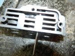
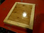
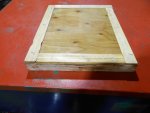
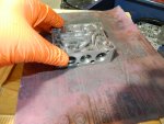
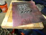
Here's some pictures of a "Sanding plate" I made up using some heavy plywood (1-1/8" ) and some paint sticks and a small pane of glass.
After setting the paint sticks in place around the glass with a 3/4" stapler, I removed the glass and made-up a large quantity of "Epoxy" and applied this to the plywood. Then setting the glass pane back in I carefully pressed the glass into the epoxy. You will need to wipe up any excess that comes out around the glass quickly. Once all the air bubbles are out leave it for a day. You now have an extremely flat surface to wet-sand your valve bodies with. I just use the cleaning solvent from my parts cleaner, and a good quality 400 grit sandpaper.

021.JPG023.JPG013.JPG014.JPG
 

rustystud

Well-known member
9,280
2,987
113
Location
Woodinville, Washington
I'm getting ready to start assembly of the transmission. There are a few things still missing at the machine shop and the gasket manufacturer, but I can assemble the oil pan.
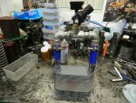
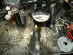
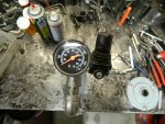
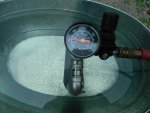
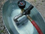
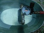
First I needed to check out the integrity of the cooler. I made up a tester awhile back and it works great for this. The "manual" says to pressurize the cooler to 35 to 40 PSI. Well these coolers are now over 50 years old and the cooling system of the engine doesn't go over 14 PSI so I only tested it to 30 PSI which is more than enough.

001.JPG002.JPG003.JPG004.JPG005.JPG006.JPG007.JPG

You can see I put the cooler in a tub of water and then pressurized it to 30 PSI and looked for air leaking out. I tested three coolers today and all worked great.
Later once the cooler is in the oil pan unit I'll pressurize everything checking for leaks.
Water in the transmission from a failed cooler system is the number one failure of the 303M transmission that I know of. Followed by the front pump. So you need to check this system extremely well. You don't want any "strawberry or chocolate shakes" in your oil pan.
 

rustystud

Well-known member
9,280
2,987
113
Location
Woodinville, Washington
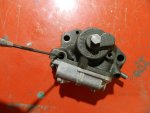
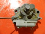
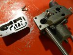
So now we're on to the Rear Servo. This little guy can be a real pain to rebuild.
This is one item I would pass on rebuilding if I didn't have the special tool. As long as it passes the air test and the apply rod retracts just leave it alone.
Since I do have the special tool it would be a dick move not to show you how to take this servo apart and put it back together.
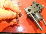
Actually it comes apart really fast ! Those springs want to be free ! That is a problem all in itself.
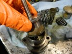
If you have an "Arbor" press you can apply pressure to the spring retainer and remove the two bolts (1/2" wrench) . Now watch out as it will try and get away from you. Once you have it apart. Clean it and check the bores. There are three that need close inspection. I just use a brake hone on all three and clean them up. There almost always scored and slightly out of round. Once all the parts are cleaned and honed then apply your assembly lube and start putting it back together.
Here's some pictures to help you out.
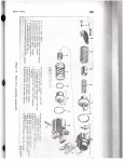
img012.jpg
First we must clean up the bores in the "Accumulator Body" (H) , the main Body (Q) , and the bore in the "Accumulator Piston" . After honing these bores, thoroughly clean them out and dry them.
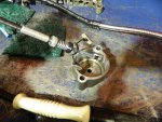
009 (2).JPG
There are three sealing rings that need replacing or buffing out. To buff the ring's take some "green scotch pads" and really go after those rings. You need a rough surface to help it seal against the cast iron housings.
Check the "Accumulator Body Check Valve" , making sure it is in place and working.

Now the first item to go together is the "booster piston". You will need to be careful as you compress the seal ring. Once it is all the way in it's bore install the inner booster spring and the outer spring. The seal ring on the end of the piston should be "centered" as best you can before installing the "Accumulator Body" . You can twist the accumulator body as you slide it in to help the seal ring go into its bore. Your pressing against those two springs so remember to hold constant pressure against the accumulator body.
Once the body is all the way down and in contact with the Main Body, loosely install one bolt to hold it in place. Make sure one side of the bolt is parallel with the bore to allow the "Accumulator Piston" to be installed. Once the "Accumulator Piston" is in place, install the "compensator spring" and then the "accumulator spring" . Now the real fun begins.
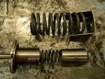
005 (2).JPG
You will need to compress the "compensator piston" into the "accumulator piston bore" at the same time the large "accumulator piston spring" is in place. This is why the special tool is so handy.
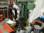
001 (2).JPG The compensator piston can easily cock in the bore so you must be very careful here.
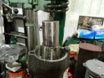
012 (2).JPG013 (3).JPG
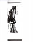
Once the compensator piston is sliding into it's bore, remove the holding bolt and you can fully compress the springs. Now install the two bolts into the retainer and your done. Pressure test the servo and if you didn't break any seal rings it should retract the apply rod.
img013.jpg
 

Attachments

Last edited:

rustystud

Well-known member
9,280
2,987
113
Location
Woodinville, Washington
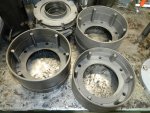
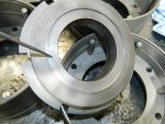
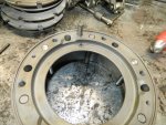
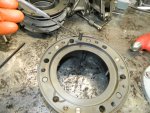
The machine shop finally finished all the work I had him do. I had 10 clutch drums and piston housings modified to "six" drive rods instead of three, and a bunch of pistons modified with the quicker apply, and other odds and ends. To save a little bit of money I installed the drive rods myself.
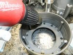
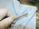
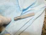
I put the rods (made out of 4140 steel) in the deep-freeze overnight and used a heat gun to warm up the housings. Then using a driver I made-up and a little lube, I drove in the rods. Worked extremely well.
I also had the ring gears on the drums modified to have the extra rod for high torque.
So now I have five sets of clutch drums modified to "GM's High Performance" standards.
Was it necessary ? No, but I would rather be "safe than sorry" when it comes to my rebuilds.

010.JPG I heated up the hole with my heat gun.
011.JPG Than taking a frozen rod I cleaned off the frost and put a little lube on the end.
012.JPG
005.JPG Than using my little installer I made, I drove in the rods.
006.JPG
009.JPG 013.JPG
The pistons came back looking great too.
015.JPG This little modification makes the piston apply faster since the fluid is already under the piston pushing against it. The HydraMatic racers in the Fifties came up with this and several other modifications. Most do not apply to our transmission. We do not need a manual shift transmission for one.

Here I'm driving in the special high torque rod.

002.JPG003.JPG004.JPG005.JPG
 
Last edited:

rustystud

Well-known member
9,280
2,987
113
Location
Woodinville, Washington
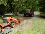
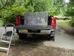
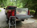
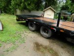
I've been working on my truck and trailer for the up-coming trip to "plowboys" place.
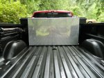
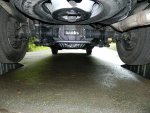
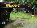
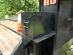
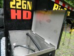
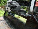
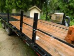
I installed a 95 gallon auxillary fuel tank, and a rear axle "anti-sway bar" on the Chevy. The trailer I installed a 12,000 Ibs winch and battery tray and box. I'm rewiring the trailer connector with a better quality one then it came with, also installing a junction box. I ordered side rails and "D" ring brackets. Everything is almost ready now.
So of course I had to have a "hip" injection today. It is going to lay me up for a few days. There is "always" something to crap on your plans.
I had originally planned leaving in late July, but the title and registration for the trailer did not arrive in time. My co-pilot (my son) had to leave for College and since I cannot drive alone anymore (long story) I needed someone else. My wife finally agreed to go with me but then our dog (her other child) needed surgery. So I decided to fix up the truck and trailer. I just hope the weather holds now.
Oh, I need to replace my truck tires now too. There just starting to hit the "Yellow" warning mark on your standard tire tread gauge. Since I will be travelling just under 2,000 miles I figured better "safe than sorry".
Always something.
001.JPG002.JPG003.JPG001.JPG

002.JPG003.JPG
004.JPG006.JPG008.JPG009.JPG
012.JPG013.JPG010.JPG011.JPG
 
Last edited:

rustystud

Well-known member
9,280
2,987
113
Location
Woodinville, Washington
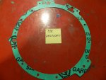
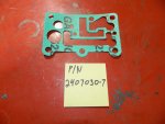
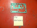
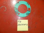
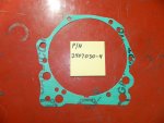
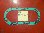
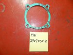
I forgot to mention, the gaskets are ready. I ordered the four sets, now you guys can order individual sets.
The company is "Gardico" in Seattle, WA.
Their phone number is 206-283-5850 ask for "Arlin Hunter". They have the set under "Military Transmission" gaskets.
The price for the eight gaskets needed for the reduction unit will cost $90.00 plus shipping.
That is a great price considering "Fatsco" will not even consider making them. I called and asked.
 

Blake

Active member
322
61
28
Location
Opp, Alabama
I forgot to mention, the gaskets are ready. I ordered the four sets, now you guys can order individual sets.
The company is "Gardico" in Seattle, WA.
Their phone number is 206-283-5850 ask for "Arlin Hunter". They have the set under "Military Transmission" gaskets.
The price for the eight gaskets needed for the reduction unit will cost $90.00 plus shipping.
That is a great price considering "Fatsco" will not even consider making them. I called and asked.

Thank you Rustystud for the reduction unit gasket set, behind the scenes work. I received a quote from Gardico today and if (1) reduction unit gasket set is purchased, the total is around $334.89 plus shipping due to the set up for (1) run and the prices range from $40.65 to $46.45 per gasket. If (5) sets are ordered, the price per set is substantially lowered to around $94 plus shipping per set. If (10) sets are ordered, there is a further discount.

I am looking into purchasing (5) sets and have commitments for (3) sets. Does anyone want to go in on a group buy to:
1) Take advantage of the (5) set price breakpoint - approximate cost $94
2) Participate in the fractional share of the initial shipping cost from Gardico to my shop in Virginia
3) Shipping to your location would be actual usps shipping charges.

Private message me if there is any interest. Thank you!
 

rustystud

Well-known member
9,280
2,987
113
Location
Woodinville, Washington
Thank you Rustystud for the reduction unit gasket set, behind the scenes work. I received a quote from Gardico today and if (1) reduction unit gasket set is purchased, the total is around $334.89 plus shipping due to the set up for (1) run and the prices range from $40.65 to $46.45 per gasket. If (5) sets are ordered, the price per set is substantially lowered to around $94 plus shipping per set. If (10) sets are ordered, there is a further discount.

I am looking into purchasing (5) sets and have commitments for (3) sets. Does anyone want to go in on a group buy to:
1) Take advantage of the (5) set price breakpoint - approximate cost $94
2) Participate in the fractional share of the initial shipping cost from Gardico to my shop in Virginia
3) Shipping to your location would be actual usps shipping charges.

Private message me if there is any interest. Thank you!
OK, that is different from what they told me. Since I ordered the initial four sets they said the individual set cost would be $90.00 . Now you need to order five sets to get that price. I need to talk with Arlin. I can have another company make-up the gaskets.
 

rustystud

Well-known member
9,280
2,987
113
Location
Woodinville, Washington
I talked with Arlin today. Basically, I was misled. He originally told me once the cost to load the specifications into the computer was met, it would be simple to replicate the gaskets and the cost would be lower than my original investment. Now he's saying every order is subject to this extra cost so you must order in quantities of four or more to get the price break of $94.00 a set.
I'll try and find another gasket maker who's more open and honest.
 

rustystud

Well-known member
9,280
2,987
113
Location
Woodinville, Washington
Well, I'm back on the rebuild. I had been spending all my time last month getting ready to go see "plowboy" in Edmonton Canada. Due to a lot of crazyness I had to abort that trip, but I was able to go see a guy in "100 mile House" Canada who had several transmissions and parts for sell. I ended up with five 303M HydraMatics and quite a few good parts.
So now I'm ready to get back on the rebuild project.

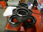
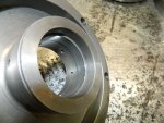
The first thing is rebuilding the clutch drums. I had to replace some bushings in the rear drum. The front drum was fine.
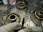
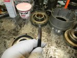
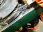
This chisel is called a "bushing cutter" . You can see the nice groove it cuts in the old bushing which allows you to easily remove the bushing.
015.JPG016.JPG018.JPG020.JPG
021.JPG They no longer make this bushing, so you need to replace it with two narrower bushings.
 

rustystud

Well-known member
9,280
2,987
113
Location
Woodinville, Washington
I'm breaking up this post since the pictures downloaded stay with the post now. Makes it really messy and confusing trying to get everything organized.

Once the drums are all ready to go it's time to install the pistons. I did have the inner seal area machined to except rubber seals but I decided to go with the Iron outer seal as the machining costs were getting expensive and I didn't have the cash to machine the pistons to except rubber seals. Mistake.
I assembled everything and even installed the assembled drums with bands into the case. After pressure testing, I found I was losing over 10% of my air which translates into hydraulic pressure. I have a "pressure leak down tester" which I connect to the air line. Now 10% is not terrible, in fact the factory allows for this amount of leakage, but we are dealing with old pumps which new parts are not available for, so this amount of leakage is not good. I ended up tearing everything down and will be having the pistons machined properly to except rubber seals.
Here are the pictures of my efforts today.
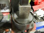
003.JPG008.JPG Installing the inner seal (rubber) and the iron outer seal.
009.JPG I forgot to show installing the clutch plates. When I go back together nect time I'll show it.
011.JPG
012.JPG022.JPGHere you need to install the small bronze thrustwasher than the steel washer which has a small "notch" which must align with the notch in the shaft. I'll take better pictures next time.
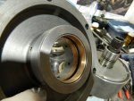
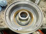
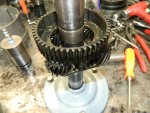
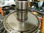
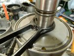
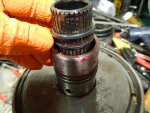
025.JPG026.JPG You really need the special tool to install the "oil delivery sleeve" . It compresses the seal rings and allows the sleeve to enter the front drum without damage to the seal rings. It also allows the rear drum to slide over the sleeve without damage to the seals.
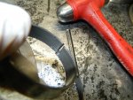
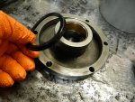
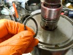
032.JPG033.JPG After the sleeve is installed into the front drum you need to install a "snap ring" on the shaft and then the "special" lock ring shown here. Do not lose this ring !
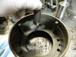
If you do lose this ring your "clutch hub" will have to much lateral play on the planetary shaft.
You can use a later civilian HydraMatics clutch hub (1952-up) which is thicker. Of course, finding this would be just as difficult as finding another lock ring. So "Don't lose this ring !"

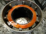
027.JPG029.JPG Here's the rear clutch drum. Just needs the piston assembly installed. A special note here about the springs shown here. The front and rear clutch drum assemblies use the same springs but the front assembly does "NOT" use the guide pins. If you mistakenly use them in the front clutch drum, they will come out through the drain holes and go into the transmission causing all sorts of horrible things to happen.
 
Top
AdBlock Detected

We get it, advertisements are annoying!

Sure, ad-blocking software does a great job at blocking ads, but it also blocks useful features of our website like our supporting vendors. Their ads help keep Steel Soldiers going. Please consider disabling your ad blockers for the site. Thanks!
I've Disabled AdBlock
No Thanks